This thread has been locked.

If you have a related question, please click the "Ask a related question" button in the top right corner. The newly created question will be automatically linked to this question.

How to check an OP-Amp is in negative feedback or not

Hi,

May I know how to check an op-amp is in negative feedback or not.

We used to say when output is connected to inverting terminal of the opamp,it is operating in negative feedback.

There are many op-amp circuits where output is connected to both inverting and non inverting terminal of the op-amp.May I know in such situations how to check and make sure that

op-amp is operating in negative feedback.

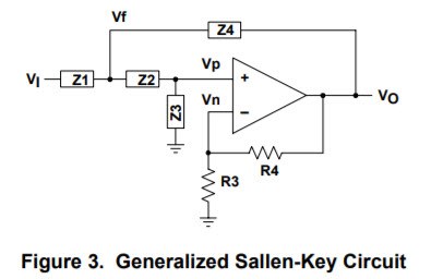
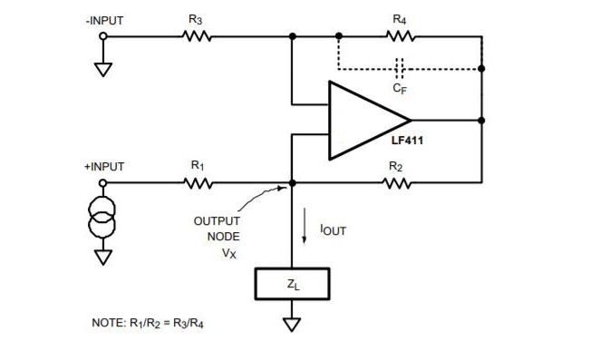
Please see the attached image.

Regards

Hari

  • Hi Hari,

    You have picked two common operational amplifier circuits that rely on not only negative feedback, but positive feedback to provide the intended function. The first being a Sallen-Key active filter and the second the Howland Current Pump. The transfer function for each of these circuits is complex and viewing them written out probably won't impart an intuitive understanding as to what is occurring with the two feedbacks. A detailed analysis of the gain-phase response vs. frequency for each circuit might be more revealing in terms of the pole-zero locations and the actual phase margin.

    The important point is that for both circuits the negative feedback must dominate over the positive in order to maintain sufficient phase and assure stability. If the positive feedback dominated it is likely the circuits would oscillate.

    Regards, Thomas
    Precision Amplifiers Applications Engineering
  • Hi Thomas,
    Thank you very much.


    I would like to know is I have an arbitrary OP-AMP circuit where output is connected to both positive and negative input of op-amp.In this case how I will check and make sure that opamp is in negative feedback.Could you please suggest some generalized method so that I can apply it to any opamp circuit.

    Regards
    Hari
  • Hi Hari,

    Yes, there is a practical and easy way to make sure that the circuit has sufficient phase margin to remain stable. If the circuit is stable and exhibits good transient response characteristics, then that is a direct indicator that the feedback characteristics are correct and doing the job.

    A method we use in the lab and for simulation is to drive the op amp circuit with a small-signal square-wave and observe its output waveform with a wideband DSO. The intended load needs to be connected because its impedance characteristics need to be included in the output response. The input square-wave is set to a level such that the output remains small-signal and doesn't go into large-signal operation. Slew rate limiting can become a factor and that will alter the results.

    For example, apply a 10 or 20 mVp-p, 100 Hz square-wave (or applicable frequency) to the circuit input. Then, observe the output from the op amp circuit with the DSO and note the overshoot on the waveform leading edges, and any ringing resulting from the overshoot.

    The TI Analog Engineer's Pocket Reference, on Pg. 49 of the 4th edition provides useful graphs that relate the phase margin to percentage overshoot. Figures 34 and 35 are the graphs you would apply to determine the approximate phase margin. The circuit would ideally have at least 45 degrees of phase margin, and you really don't want less than 30 degrees for most applications.

    You can find the Analog Engineer's Pocket Reference here:

    Regards, Thomas

    Precision Amplifiers Applications Engineering

  • Hi Thomas,

    Thank you very much.

    I will restate my question in another way. Please find the attached image of Howland current pump.

    I removed the signs of the opamp.

    My question is I need to determine the signs of the opamp such that the system works in negative feedback.

    Regards

    hari

  • Hello Hari,

    I am not sure that an analysis that doesn't include the operational amplifier input signs makes sense. You wouldn't know if the output is inverted, or in the same phase as the input, which is important to know with regard to negative or positive feedback.

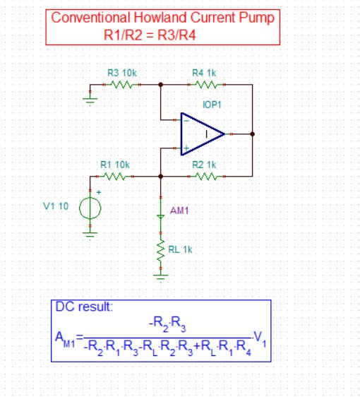
    I show below the transfer function for the conventional Howland Current Pump and you will note that there are minus signs in the equation. That indicates that sense of the feedback has been taken into account.

    I have attached a PowerPoint slide set that provides the derivation of the transfer function for a dual-feedback system. It allows one to determine the output voltage for an input voltage that takes into account the effects introduced by the negative and positive feedback factors.

    Regards, Thomas

    Precision Amplifiers Applications Engineering

    Dual Feedback Beta Derivation.pptx

  • Hello Hari,

    For the complete story regarding dual-feedback stability analysis see the attached PowerPoint. Slides 100 through 114 are specifically about op amp dual-feedback stability analysis.

    This stability slide content was developed by Tim Green, the Precision Amplifiers Applications Engineering Manager, and Collin Wells, the General Purpose Op Amps Applications Manger. There is a great deal of information about op amp stability issues covered by these slides.

    Regards, Thomas

    Precision Amplifiers Applications Engineering

    Solving Op Amp Stability 2013 TG_RevB.pptx

  • Hi Thomas,

    Thank you for your time and concern.

    Could you please go through the attached document from page 3 on wards, and will tell me how to find the op amp signs for Figure-12.

    Opamp Sign.pdf

    nptel.ac.in/.../104

    Regards

    Hari

  • Hello Hari,

    I must admit when I review the paper you reference I am confused about the purpose of establishing the "SIGNS OF OPAMP TO PROVIDE NEGATIVE FEEDBACK IN A LOOP" in the manner in which it is presented in the material. Conventional op amp practices based on control loop theory establish which input on the op amp results in negative feedback, and that one is indicated by the negative sign symbol. Certainly there can be enough phase delay in a feedback circuit such that the feedback is no longer negative and becomes positive, resulting in instability. But at least that can be fully analyzed using gain-phase plots with respect to the inverting, or non-inverting input which are established up front.

    The problem in Fig. 12 is an academic exercise which doesn't seem to be complete. There isn't any input voltage (Vi) or current (Ii) source, only Vo; therefore, it is not clear what this particular circuit's function is and what it is supposed to do. You will note that all of the other figures in the article have input sources and an expectation of an output voltage or current. I do not think it is a good use of time trying to determine the signs on the op amp inputs when it is not known what function the circuit is supposed to be.

    Regards, Thomas

    Precision Amplifiers Applications Engineering

  • Hi Thomas,

    Thank you very much.
    May I know how to determine the signs for figure 10

    Regards
    Hari
  • Hello Hari,

    Actually, the author provides the solution for the circuit shown in Figure 10 on pages 4 and 5:

    "In fig(10),there are two opamps. First we have to determine the signs of one opamp assuming all other opamps are ideal. Let opamp(1),assuming opamp(2) as ideal, then:

    Vid1 = −Vo1(R3 R4) [R1 / (R1+R2)]

    So we connect this to positive terminal. Now we know the signs of opamp(1). To dermine the signs of opamp(2),

    Vo1 = Ao(Vo2) [ R1 / (R1+R2)]

    Vid,2 = Vo1 [R3 / (R3+R4)] + Vo2 [R3 / (R3+R4)]

    So we connect this to negative terminal of the opamp(2)."

    Regards, Thomas

    Precision Amplifiers Applications Engineering

  • Hi Thomas,
    Thank you very much.
    Could you please ellobrate the above equation . May I Vid1 is the difference voltage between inputs of first opamp.
    Could you please tell me how you obtained the value of Vid1.
    Regards
    hari
  • Hello Hari,

    We know for the circuit to be stable that the feedback to A1 needs to be negative. The output from A1 was expressed as:

    Vid1 = −Vo1 (R3 R4) [ R1 / (R1+R2) ]

    Vo1 is set negative so that A1 operates with negative feedback, thus it appears as -Vo1 in the equation. The signs on the op amp must be set up so that the A1 summing node receives negative feedback from the loop. The A1 output Vo1 is then applied to the R4 node in the circuit at the input of A2. The voltage gain of A2 is the ratio of R3/R4, the second term in the equation above. Vo1 is amplified by that ratio which produces the Vo2 voltage level. The last term in the equation is [ R1 / (R1 +R2) ]. Vo2 is divided by this ratio and that voltage is the Vid1 differential voltage applied to the A1 input.

    A1 is set up with the non-inverting input acting as the summing node, or inverting input. It sums the input voltage Vi with the feedback voltage appearing at the R1, R2 junction. Figure 11 in the paper shows the op amp input signs needed to satisfy the negative feedback condition around the A1, A2 loop. 

    Regards, Thomas

    Precision Amplifiers Applications Engineering

  • Hi Thomas,
    Thank you very much.
    If you don't mind could you please explain the above derivation with the help of circuit diagram.
    May I know why A1 needs to be in negative feedback.
    Regards
    Hari
  • Hello Hari,

    It appears that I am not communicating effectively regarding your negative feedback questions. Your may benefit more and improve your understanding from some on line resources that do a very good job of explaining the concepts of negative and positive feedback.

    One resource that I find particularly good on the feedback subject is provided on the Electronics-Tutorials web site. You can find the link here:

    This is Section 4, but be sure to view Section 5 as well. It builds on Section 4 and covers negative feedback systems.

    Regards, Thomas

    Precision Amplifiers Applications Engineering 

  • Hi Thomas,
    I never meant your explanation is not clear.If anything wrong happened from my side,please excuse. I am an average person that's why it's taking time to understand.I will spend this weekend to understand this issue and will get back to you.
    Regards
    Hari
  • Hi Thomas,

    Thank you very much .I analysed the problem with the support of your material.

    Could you please check the attached document and tell me my approach is wrong or not.

    Sign.pdf

    Regards

    Hari

  • Hello Hari,

    I am glad to see that you are analyzing the circuit. That is the best way to learn and understand how it works.

    The two equations you have written are correct except that the A2 closed-loop gain term in each equation should be R3 / R4, not R3 / R4. I think that will be apparent when you look them over.

    Regarding your statement, "For negative feedback to exist phase shift around the loop must be 180. " That isn't exactly correct. Picture an op amp connected as a simple inverting amplifier. At dc and very low frequencies the output voltage moves in the opposite direction to the voltage applied to the input point of the input resistor. The output is truly 180 degrees out of phase with the input. However, as we increase the input frequency the dominant pole response of the amplifier introduces phase shift that increases as the frequency is increased further.

    The dominant pole of the op amp adds 45 degrees of phase shift at the dominant pole frequency (-3 dB) which is added to the 180 degrees. That results in 225 degrees of phase shift between the input signal the voltage fed back to the inverting input (summing node). Ultimately, at about 10x the dominant pole frequency a total of 90 degrees of phase shift is added to the original 180 degrees, for a total of 270 degrees. Keep in mind that the feedback is still negative. if the 270 degrees is subtracted from 360 degrees, that is the phase margin of 90 degrees.

    If another pole is added into the feedback loop it will contribute phase shift as well. This can happen when a pole is contributed by the open-loop output resistance (Zo) in conjunction with an external output load capacitor, or from the feedback resistor in conjunction with the op amp input capacitance. If the additional pole contributes an additional 90 degrees of phase shift at a low enough frequency where the op amp still has open-loop gain (Aol) remaining we have the original input to output 180 phase shift, the 90 degrees from the op amp dominant pole, and the 90 degrees from the second pole or 180 + 90 + 90 = 360 degrees. In this case the phase margin has gone to 0 degrees.

    Three-hundred, sixty degrees of phase shift means the feedback signal is now exactly in phase with the input signal. That is the positive feedback condition.

    Therefore, as long as the total phase shift stays less than 360 degrees, the feedback is still negative. Typically, we like to design an op amp circuit such that the phase margin is at least 45 degrees.

    These concepts were covered in the Stability Analysis Excel file that was attached to an earlier response.

    Regards, Thomas
    Precision Amplifiers Applications Engineering