This thread has been locked.

If you have a related question, please click the "Ask a related question" button in the top right corner. The newly created question will be automatically linked to this question.

OPA549: OPA549 Application Questions and Roadmap Advisory

Part Number: OPA549

Hi team,


Nice to reach out to you. My customer is doing a pre-research project and will use our OPA549, to generate a programmable low voltage and high current power source.

They have below questions which need your help:


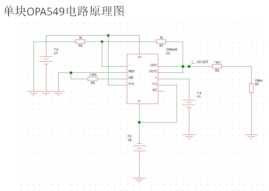
Testing schematic:

1.       Accuracy of the current-limiting resistance

Below are the measurement results:

RCL(Current-limiting resistance)

VCL Theory

VCL Test

Isupply

Iout Theory

Iout Test

Vset

1870Ω

0.948V

7.25A

8A

7.11A

ref+0.95V

940Ω

0.529V

0.520V

7.91A

8.89A

7.75A

867Ω

0.492V

0.490V

8.31A

8.97A

8.16A

845Ω

0.481V

9A

ref+0.48V


If RCL=1870 Ω, the Iout should equal to 8A in theory, but the measurement result equals to 7.11A. Why there is the difference? What’s the error range for the RCL?

 2.       How the output load influences the (V+)-Vo value?

Are there any requirement for the output load? Customer tested the voltage difference (V+)-Vo under the Iout=8A, with the output load 150m Ω , and (V+)-Vo=5.5V, which higher than the datasheet value, max output voltage swing is 4.3V. Will it cause any risk to the device?

They also tested below data:

When the output load increases to 300mΩ, the (V+)-Vo = 4.5V

When the output load decreases to 10mΩ, the (V+)-Vo = 7V


3.  They want to use OPA549 in parallel. How many pieces can be connected in parallel? Considering customer will have 8A output current for 1 piece. Are there any matters which they need to pay attention to?


4.  Do we have any roadmap for High-Voltage, High-Current Operational Amplifier?


Looking forward to your reply. Thanks!


  • Hi Susan,

    Thomas wrote a very interesting post about the paralleling of several slaves:

    e2e.ti.com/.../716405

    Referring to the current limiting feature of OPA549:

    In the electrical characteristics on page 3 of datasheet of OPA549 the current limiting tolerance is specified to be +/-500mA maximum at a current limit of 5A. See also the footnote (1) which tells that the measurement was done at 25°C junction temperature (high speed test).

    Then, on page 4, you can see how the current limiting depends on the supply voltage and the temperature.

    So, observing a current limiting at 7.11A instead of 8A appears to be within the tolerances of the chip.

    You should also keep in mind, that your circuit is suffering from a huge heat dissipation. With a load resistance of 150mR and an output current of 8A an output voltage of 1.2V is produced. But this means that 7.6V - 1.2V = 6.4V is dropping across the OPA549. In combination with an output current of 8A this results in a heat dissipation of 51W within the OPA549! The thermal resistance from junction to case is 1.4°C/W. So, even with an ideal heatsink the junction would heat up by 1.4K/W x 51W = 71K. With an ambient temperature of 40°C this would mean a junction temperature of 111°C, an ideal heatsink assumed! With a real world heatsink of 1K/W, which would be huge, the junction would heat up even more, by additional 51K to 162°C. This is well beyond what would be recommended for a reliable application.

    Kai

  • Hello Susan,

    Kai provided good answers to your questions. I would like to add a few more comments.

    1.       Accuracy of the current-limiting resistance - If RCL=1870 Ω, the Iout should equal to 8A in theory, but the measurement result equals to 7.11A. Why there is the difference? What’s the error range for the RCL?

    The OPA549 current limit function is not a high precision function. The current limit tolerance is only specified under one specific condition:

    Current Limit Tolerance(1)  ±200 mA  typical,  ±500 mA maximum, and this is for the condition where RCL = 7.5kΩ (ILIM = ±5A), RL = 4Ω, and NOTE (1) High-speed test at TJ = +25°C apply.

    Thus, for this specific condition the tolerance can be as high as 10 %. If this 10 % tolerance were applicable to the 8 Ampere condition we could expect about as much as 800 mA variance from the equation value. An actual 7.11 Ampere result is reasonable. Do note that the OPA549 specifications do not assure the current limit accuracy under any other conditions. The CURRENT LIMIT vs TEMPERATURE and CURRENT LIMIT vs SUPPLY VOLTAGE graphs on Pg. 4 reveal a bit more information about the "Typical" current limit behavior.

     2.       How the output load influences the (V+)-Vo value?

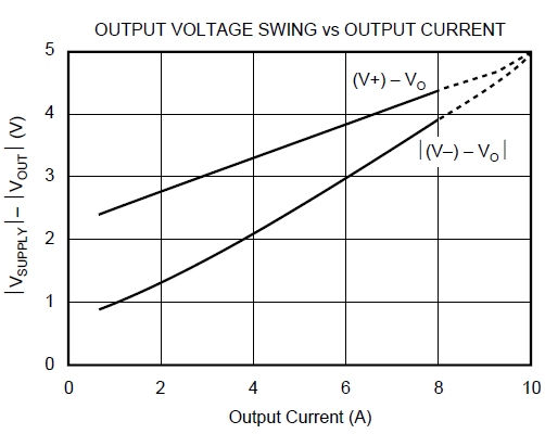
    The OPA549 output transistors, like all bipolar transistors, have collector-to-emitter resistance. As the current demanded by the output load increases the voltage drop across that internal resistances increases limiting how close the output can swing to the supply rails. This is reflected in the datasheet graph that have shown.  

    3.  They want to use OPA549 in parallel. How many pieces can be connected in parallel? Considering customer will have 8A output current for 1 piece. Are there any matters which they need to pay attention to?

    Fig. 14 in the datasheet shows an example of two OPA549 devices in the master/slave configuration. Even though two OPA549 op amps can handle an output current approaching 20 Amperes, handling the high power dissipation that can occur can challenging as Kai explained. The heat management will likely become the more difficult part of the design.

    4.  Do we have any roadmap for High-Voltage, High-Current Operational Amplifier?

    I am not allowed to disclose information such as this on the E2E forum. I suggest you contact Precision Amplifiers Marketing, and they should be able to assist you with your question.

    Regards, Thomas

    Precision Amplifiers Applications Engineering

  • Susan

    We haven't heard back from you so we assume this answered your questions. If you need more help just post another reply below.

    Thanks
    Dennis