This thread has been locked.

If you have a related question, please click the "Ask a related question" button in the top right corner. The newly created question will be automatically linked to this question.

Microgram Scale design

Other Parts Discussed in Thread: TIPD188

Good DAY.

I need some help with an old project that i found on your site.

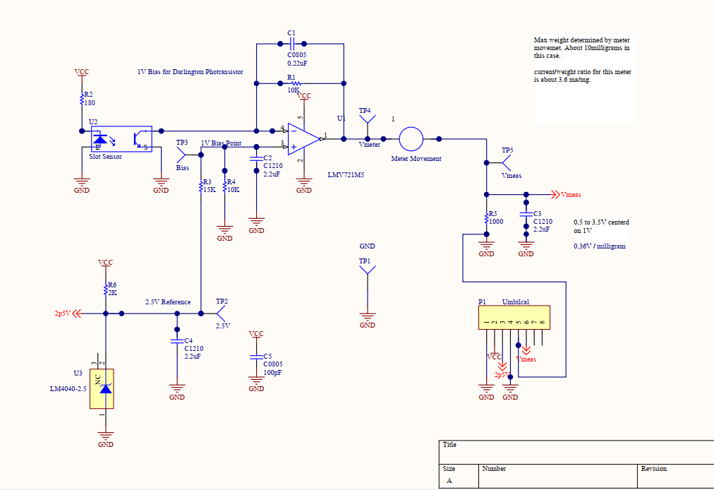
I want to build a micro gram scale. The hardware is not a big problem, but i need to know where i can get the code for the micro controller.

I also would like to know if the power supply that drives the electronics for the panel meter is a +5  0  -5 volt supply. I found the meter control circuit on this site but no circuit for how to connect micro controller and LCD to meter circuit. 

Thank you.

Christiaan. 

  • Hi Christiaan,

    can you give a link to the circuit?

    Kai
  • Hello Christiaan, 

    Please provide the identification numbers of these circuits you found on ti.com.  Also provide a block diagram of the product you are designing as this will be very helpful to determine what is required. 

    If you look through the TI, Reference Designs, you may find one that matches what you are wanting to design.  Many of these Reference Designs include software/firmware.  For example, the TIPD188 Weigh Scale has all the hardware and software available on the Product page: http://www.ti.com/tool/TIPD18 .  

    I hope this helps with your design process.  Please keep in mind that when you find a Reference Design that may be similar to what your requirements are, in the end, you will still have to write your own code, or at least modify the provided code.

    At your service,

    ~Leonard 

  • Good day Leonard.

    I am new to this site so i do not know exactly how to paste links or attachments here. every time i try to, it just sows me a funny screen, so i tried it my way and hopes it works.

    If it did not work, can you please explain to me how to do it or can i email you.5228.0118.Scale_Schematic.pdf 

  • Hi Christiaan,

    click the button "Insert Code, Attach Files and more...". Move the cursor to the line where you want to insert the file. Then click the button "paper clip" ("Insert File") in the header of input box.

    If it doesn't work properly, insert or add some blank lines. The "insert file" feature is bit weird here...

    Kai

  • Hello Christiaan, 

      I am a bit confused; you started an inquiry on this E2E thread: https://e2e.ti.com/support/amplifiers/f/14/t/766772  , but you seem to have replied to it on this totally different thread.  Are the two related?  

    To assist with learning how to use E2E, on the top red banner, click on Forums, and then Site Support.   You will see four FAQs at the top of the list, please read through these.

    [FAQ] Getting Started in E2E

    [FAQ] How do I ask a question on E2E?

    [FAQ] E2E Search Advanced Tips and Tricks

    [FAQ] What are the guidelines for posting on E2E?

    ~Leonard 

  • Hello Christian,

    The TIPD188 is an amplifier for strain gauge based scales and not related to my "force displacement" milligram scale.

    VCC is +5V for the entire board. No "split" supplies are required.

    The VGA devices used in the motherboard are now long obsolete. But basically it just amplified the VMeas output and stuffed it into an A/D. The INA guys can probably recommend a good replacement VGA (PGA series). The LMP8100 VGA used had 16 gain ranges. Even though I designed with two VGA stages, I ended up only using just the one VGA and it's 16 gain ranges.

    The actual scaling will depend on the meter movement used. The idea is simply that the more weight applied to the "scale" (forcing the needle down), the more current is needed to move the needle back to level. The current required is converted to a voltage by R5.

    Please close out the other thread. We can continue here.
  • Good day Paul.
    Thank you for your reply. I am very much interested in the meter movement circuit diagram.
    I would like to know a few things. #1 From what i understand from this circuit diagram, is that , this circuit can operate on its own with the power supply circuit, but with out the micro controller. With a DMM you can measure the milli volts needed to zero needle and then add weight and measure with DMM the voltage difference needed to zero needle again and calculate weight. #2 If the above statement is true, is there any changes needed to be made to the circuit to accomplish this. I saw the complete circuit diagrams eventually. a bit of dumb moment for me to take so long to find it on your site. I am not so much interested in 100% accuracy . I kneed very good consistency . #3 Will 2p5V and U3 be omitted?

    If you have any questions about the above, please let me know. I need to weigh small model parts that i make for myself.

    Thank you.
    Christiaan.
  • Hello Christiaan,

    Forget that schematic entirely; it is not the shortest path to success. Start with a microgram sensor (of your choosing) and use their suggested circuit to get an analog voltage or PWM or whatever its output may be. Then pick a TI microcontroller board  (of your choice). There should be example code for the microcontroller to read in analog or PWM. If you need help with that code start a new post.

    http://www.ti.com/tools-software/launchpads/overview.html

  • Hello Christian,

    Yes. The circuit shown can operate on it's own. You will need a *stable* reference voltage, so R6 and U3 are needed. Do NOT just divide down the supply voltage. You need to apply about 1V to the amplifier positive input (depends on your meter movement). This sets the "zero" reference current through the meter movement.

    The meter movement is mounted on it's side, so "zero" level is roughly about 20% full-scale if the meter was upright. So if you used a 1mA meter movement, then "zero" would be 200uA. The 200uA (or whatever you will need) is determined by R4 and the 1V reference voltage. The currents should be as low as possible to minimize self-heating of the coil, but high enough to have enough motive "strength" to lift the load.

    The actual mechanical "zeroing" of the scale movement is done by sliding the optical sensor so that the needle (beam) is level. Whatever voltage is across the resistor at that time is the "zero" (tare) voltage and should be subtracted from the actual measurement.

    In the motherboard circuit, when the "zero" button was pushed, there is a D/A that generates a similar "zero" voltage that was used to subtract the offset. The amplifier then amplified the difference between the two.

    So if the "zero' voltage was, say, 360mV, then the D/A was set to 360mV, and the following amplifier only had to amplify the difference - allowing greater measurement resolution (dynamic range). This nulling voltage should be derived from the same reference as the 1V reference voltage.

    For example, if you try to measure the 360mV across R4 with your DMM, you will need to be on the DMM 2V scale, which probably gives you 1mV resolution for a decent DMM. 360mV of your meters range (dynamic range) is wasted with the zero voltage.

    If you connected the DMM between R5 and another +360mV source (either a pot or D/A), then the resulting reading is closer to zero and the meter will now be on the 200mV, or even 20mV scale , giving you 100uV, or 10uV resolution.

    So you basically:

    1. Zero scale mechanically so that the beam is level
    2. Measure the voltage across R5 - this is Vzero
    3. Apply weight
    4. re-measure votlage across R5 - this is Vloaded
    5. Vtare = Vloaded-Vzero
    6. Weight = Vtare * scalefactor

    Scalefactor will need to be determined using known weights, and will be in V/mg or similar, and will be completely dependent on the meter movement used.

    For my scale, it was 360mV per milligram, or 360uV per microgram. So you can see what a difference 1mV and 10uV resolution would make as far as resolution if I did not null the zero voltage.

    Also - if you want consistency - you MUST place the weight in the *exact* same spot on the beam so that the distance to the fulcrum is the same. Otherwise, too far out will result in a higher reading, and too far inwards a lower reading (think: leverage). You must mark a "cal spot" spot on the tray or beam and place the weight directly over it every time. That is why balance scales use a tray...

  • Good day Paul.
    I am a bit confused now. I read in a post of yours ( Jul 31, 2013 5: 19 PM ) between you and Matthew Derstine that for the best results you have to measure between V meas TP5 and the 1 volt reverence input Tp3 but now i must measure between R4 and another +360 mV source through a pot?????? Where and how do i change the circuit to do this and where do i get the +360 mV from?
    What is TP1 and V CC, c5 c0805 100 pf to ground and TP2 2.5 V for? I assume that the 2P5V connection point is not necessary without the micro controller circuit but V CC R6 and U3 is definitely needed. What is TP4 used for?
    The stable 1 volt reference needed on the + input of the amplifier, does that derive from the same power supply through R6, U3 and R3 or a separate supply or is that 2p5V through a pot. (variable power supply. )?
    I have noticed that that all the ground points of the power supply have cap numbers and values and the meter movement circuit ground points also have cap numbers and values assigned to it, so i assume the matching values connect to each other (common ground )? I assume that without the micro controller circuit, pin 5 on Umbilical P1 is not used? ( looks like a common ground to me, same as pin 1 and pin 4. )

    The rest of circuit and your explanation make sense to me.

    Thank you.
    Christiaan.
  • Hi Christiaan,

    OOPS...Above I was saying R4 - I meant R5 - the 1000 ohm resistor after the meter coil. Perhaps that was your confusion. Sorry..I'll correct the text above.

    We are going to need to move this off-line, as this forum is for TI products, and this is not referring to any specific TI devices. Do you mind if I contact you at your registered email address to continue? If so, please click the "resolved" button to close out this thread.

    The meter movement has a resistance, which will drop a certain amount of voltage. So the amp output (1V) and the top of R4 will have different value depending on the drop across the meter coil. The 1V may need to change depending on the meter drive.

    The voltage across R5 with no load is the "zero" voltage. That will depend on your particular meter movement. This is the voltage you need to subtract from subsequent measurements.

    This project was the first I did in Altuim Designer for Schematic and PCB layout, before we had full libraries, and I was still learning. So I used "generic" symbols and cut-pasted, of which several had their SMT package type still displayed (C0805, C1210) and I did not hide them. So you can ignore those - they are footprint referecnes.

    The C5 100p cap is a ceramic supply bypass cap for the amp - I just needed the pad and did not change the value (all ceramic bypass caps are 0.1uF).

    The "caps" are power connectors and the "arrows" (-<<) are off-sheet node connectors. All are (invisibly) connected together if the have the same name. So all the "VCC" "tees" are connected together and all the GND are connected together (there is only one GND in the circuit). The 2p5V << -- on the left is connected to pin 3 of the "umbilical" connector. Same for Vmeas and pin 6. This is common in schematics to minimize clutter.

    All the supplies on the schematic are fed from VCC, which is 5V. One 5V supply can power everything on the board.

    The 2.5V is created by R6 and U3 from the VCC line. The 2.5V was passed to the motherboard to feed the D/A converter reference input.

    The TP's are test points - little hooks where you can grab on with a clip to measure with a meter or a scope. This is better than trying to probe individual pins on the amp with a probe and possibly slipping and shorting pins. They are not needed for operation but a definite convenience when troubleshooting (and good practice - even if it is just a empty pad to solder to or probe).
  • lmp7702.pdflm4040-n.pdfGood day Paul.

    Yes, you may contact me on me email please.

    I have just a few more questions and data sheets of a amp and U3 that i found in South Africa. Please see if these components are compatible.