This thread has been locked.

If you have a related question, please click the "Ask a related question" button in the top right corner. The newly created question will be automatically linked to this question.

LM324: Unity Gain Amplifier design query

Part Number: LM324

Hi,

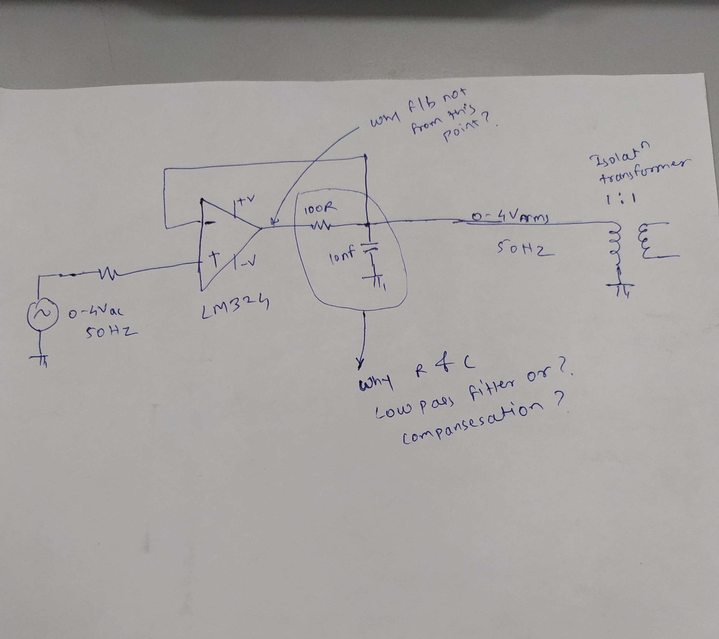
I have reference circuit of Unity gain amplifier using LM324 as shown in Fig. It is used to drive isolation transformer. In this circuit R and C is used at output of amplifier.

I want to understand use of R and C , is it low pass filter or any compensation for inductive load driving. Because feedback is taken after R and not from output terminal of OP-amp.

Regards,

Swaminath

  • where did you get this circuit? Looks the start of a dual feedback circuit but missing the cap? 

    The transformer is a short at DC, so perhaps the 100ohm is meant to limit current? to understand AC performance, the load and turns ratio are required. 

  • Hi Swaminath,

    your circuit reminds me of a negative impedance converter (NIC) discussed here:

    sound.whsites.net/.../audio-xfmrs.htm

    Unfortunately, NICs are highly instable because even the least load capacitance will increase the phase lag within the feedbak loop and by this erode the phase margin. I'm not only talking about load capacitance sitting on the primary side of transformer but also on its secondary side. So, unless the load on the secondary side of transformer isn't very well known or controlled it's not wise to use a NIC for driving a transformer.

    Kai
  • Hi Swaminath,

    If you're trying to create a buffer, then you are correct that the feedback point needs to be moved. As others mentioned, I'm not sure where you found this circuit but it seems incorrect for what you're trying to do.

    I would look at this cookbook circuit for designing a buffer: www.ti.com/.../sboa269a.pdf
    Be careful with such a large capload, you may need to compensate it.

    Finally, as mentioned by Michael, the transformer is a short at DC so depending on what signal you're trying to pass you'll want to make sure that your circuit behaves the way you expect at DC and you're not tying the op-amp output to directly to ground.

    Best,
    Paul
  • All correct, transformers are by definition AC coupled devices - so normally you have a blocking cap going into them if the source can produce a DC current.