A related question is a question created from another question. When the related question is created, it will be automatically linked to the original question.
If you have a related question, please click the "Ask a related question" button in the top right corner. The newly created question will be automatically linked to this question.
XTR116: Problem of heat generation of Q1 external transistor
Part Number: XTR116 Other Parts Discussed in Thread: XTR111
Only the power supply+24V was input, and the Q1 generates heat on the board.It is very hot. Is there a problem with the circuit? Q1 uses BCP56. XTR116 is used for 4-20mA.
Thank you for your post. Is the Q1 BCP56 in the SOT-223 package? Can you share a picture of your layout? It's important for this package type that you use larger copper pads to reduce thermal resistance and improve power performance. You can read more about this in the following Application report: http://www.ti.com/lit/an/snva036b/snva036b.pdf
Thank you for your suggestions.
However, terminal 3 is not connected to the external 24 VDC power supply GND.
It is connected to the system GND of the Instrumentation-amp.
Is it not functional if you float it?
I saw the thread and understood it well.
The power supply of the instrumentation amplifier seems to be able to clear the problem by connecting it to the REG terminal from XTR116 and 0V to the Iret terminal.
The output from the Instrumentation Amplifier must also be input to the CPU at the same time.
The CPU's reference voltage will be GND (system GND), making it impossible to connect.
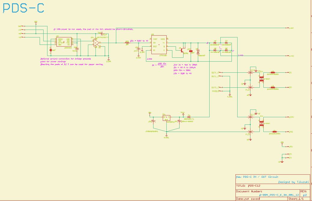
can you give us a complete schematic which also shows what you connect to the input of XTR116? And we need to be able to desipher the signal names. Can you make them clearer in your schematic? Also, where exactly is the loop resistance (4...20mA load) connected to?
Whatever you connect to the input side must be completely powered by Vref (pin 1) or Vreg (pin 8) of XTR116 as shown in figure 1 of datasheet. When you want to connect external circuitry to the input of XTR116, you need to provide galvanic isolation as shown in figure 3 of datasheet. Take this figure serioulsy. It's no joke.
Or you can take a non loop-powered voltage to current converter, like the XTR111, e.g. This converter is free from these restrictions.
The attached circuit drawing has not been corrected from Kai. In this circuit, the heat generated by the external transistor and LDO will increase. I will change to XTR111.


 Only the power supply+24V was input, and the Q1 generates heat on the board.It is very hot.