Other Parts Discussed in Thread: LM358
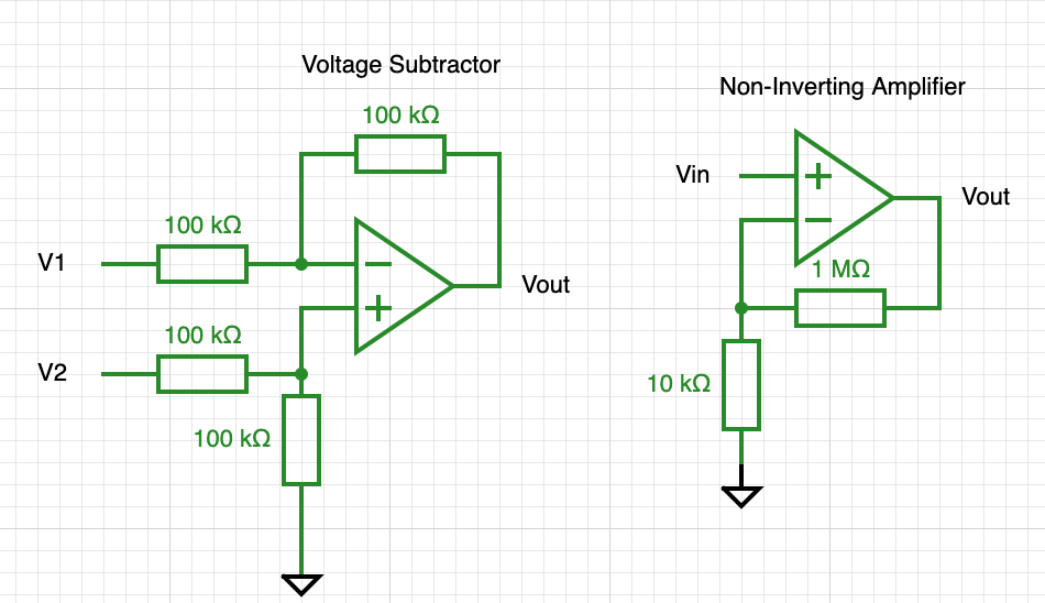
I will preface this all with I am a mechanical engineering student that is working on an electronics project so I can use all the help you are willing to give me, ha! I have attached the two schematics. For purpose of this question I have separated the two op amps, however in the actual circuit the output of the voltage subtractor is meant to be the input for the amplifier. I have been running tests and running into problems. The voltage subtractor seems to be working well on its own, however when using Op Amp A I get a 6% error, and with B I get a 24 % error which is odd, any idea why this is? The larger question however lies with the amplifier configuration. When using this amplifier, for testing I put 50 mV in and expected a gain of 101 to 5 V, but instead I was getting a gain of 67 to an output of 3.75 V which is a 33% error. I also tried a configuration with 0.93 V in and received 3.71 V out which is a gain of 3.98, when I was expecting a gain of 5.7 which is a 20% error. For reference I am supplying the single mode op amp with 5V for Vcc. My power sources are arduino Uno's since they give a pretty constant voltage source. Again I have very minimal electronic background so any and all suggestions are greatly appreciated! Thanks in advance!