This thread has been locked.

If you have a related question, please click the "Ask a related question" button in the top right corner. The newly created question will be automatically linked to this question.

VFC110: IC batch differences - maybe problem with our design?

Part Number: VFC110

Hello,

I have a possible technical problem with the VFC110 IC.

Basically the problem is the same as the one Mohamed Ozayou asked some time ago.

The link to the original question:

This issue was closed because Mohamed didn't clarify what is meant by "some batches don't work anymore".

So now he problem is somewhat escalated and the situation is:

- We tested that the VFC110 from the following batches can't be used in our circuit:

87Z36DW    
87Z36FW 
87Z36HW

- Other (maybe older?) batches of ICs works just fine and the circuit is originally used from 2004 and the actual problem started to happen just with the new batches of VFC110 (on the boards we now have sockets for the ICs so we can test which ICs can be used).

- Unfortunately I don't know what the exact problem is - I suppose that the IC don't generate output frequency (?). (I have no access to the physical boards.)

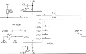
Out circuit for the VFC110:

The input signal for the VFC110 is from an AD548KN opamp output.

The VFC110 output is  connected to a 74HC08 logic gate.

I checked the circuit with the VFC110 datasheet, but I see no evident problem.

Maybe you will have some idea what the problem can be...

Thanks,

Mikuláš Reichel

  • Hi Miklos,

    before I give a longer answer, what is the frequency range?

    Kai
  • Hi Kai,

    unfortunately I don't know the technical parameters for the circuit.

    According to the IC datasheet the way we are using the IC is for the full frequency range 0-4MHz - but that is evident to you too, I suppose.
    In any case I forwarded this question to the people who may know more about the actual circuit, hopefully.

    Thanks,
    Miki
  • Hi Miklos,

    I see several issues:

    1. 4MHz is HF and your circuit needs to use HF techniques, like providing a solid ground plane, using ferrite beads in the supply voltage lines, etc.

    2. Connect both the analog and digital ground of VCF110 to the solid ground plane.

    3. You should take care that the input voltage of your VCF110 circuit does not exceed the input voltage range 0...10V.

    4. R35 must be mounted closest to pin 1. Though, I would omit R35 at all and would only use the internal resistance, when running the VFC110 at 4MHz.

    5. Increase the supply voltage decoupling caps to 100...220nF.

    6. The pull-up R3 is too small. I would increase it to about 1k.

    7. Insert an isolation resistance of about 1k between the output of VCF110 and the input of 74HC08.

    8. It's no good idea to use sockets for the VFC110.

    Kai

  • Hello Miklos,

    We certainly need more of an understanding of what "can't be used in our circuit" constitutes. We can't even begin to speculate about the quality of a VFC110AP without any substantial information to act on.

    It appears that there has been previous successful usages of the VFC110AP using the circuit schematic you provided so maybe something has changed. Semiconductor processes do move within process control limits and that is completely normal. Those process variances can affect the electrical operating characteristics of the VFC110AP, but that is accounted for in the specifications. What process shifts are good at detecting are marginal circuit designs. It may be that normal variations in these particular VFC110AP lots are exposing some electrical performance limitation of the circuit design.

    Kai has provided a number of excellent suggestions regarding optimization of the VFC100AP circuit to obtain performance full out to 4 MHz. They can serve as a starting place in troubleshooting the circuit. Do try and locate some VFC110AP devices from lots that are known to perform as expected and do an A-B-A replacement. See if things begin to operate as expected when device B is in place. With A back in place, changes made in accordance with Kai's suggestions can be evaluated for effectiveness.

    Please let us know if the listed lots were purchased directly from TI, or one of TI's Authorized Distributors. If they were purchased through another source, that could point to a problem.

    Regards, Thomas

    Precision Amplifiers Applications Engineering

  • Hello Kai,

    thank you for the suggestions.
    I am sure we will try the ones which can be applied without modifying the PCB.

    Miki
  • Hello Thomas,

    thank you for the insight.
    We are in the process of searching the best way to resolve the issue with the VFC110s and when I will know more I inform you what was the cause of the problem.

    Regards,
    Miki
  • Hi Miklos,

    I hope you have already a solid ground plane?

    Kai
  • Hello Kai,

    I checked the PCB specs and yes fortunately we have on the boards where the VFC110 ground planes.

    Regards,

    Miki
  • Hello Miklos,

    I think we have gone as far as we can for now with this VFC110 issue. Once you have more information gathered regarding the devices that do and don't function in your application, we can better address the issue.

    It would be helpful to us if you could close this e2e inquiry for now, and then open a new one once you have a more complete understanding of the issue.

    Regards, Thomas

    Precision Amplifiers Applications Engineering 

  • Hello Thomas,

    I agree.

    Than you all.

    Sincerely,
    Miki