This thread has been locked.

If you have a related question, please click the "Ask a related question" button in the top right corner. The newly created question will be automatically linked to this question.

INA260: Current monitoring connection

Part Number: INA260
Other Parts Discussed in Thread: TPS62821, CC3220SF, INA226, INA233, INA231

Hi, guys. It's my first time using the INA260. I'm trying to create a custom PCB that uses micro USB 5V.

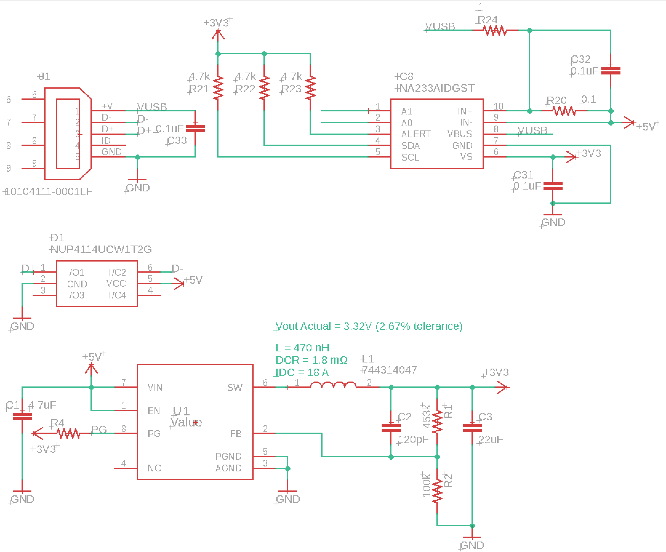
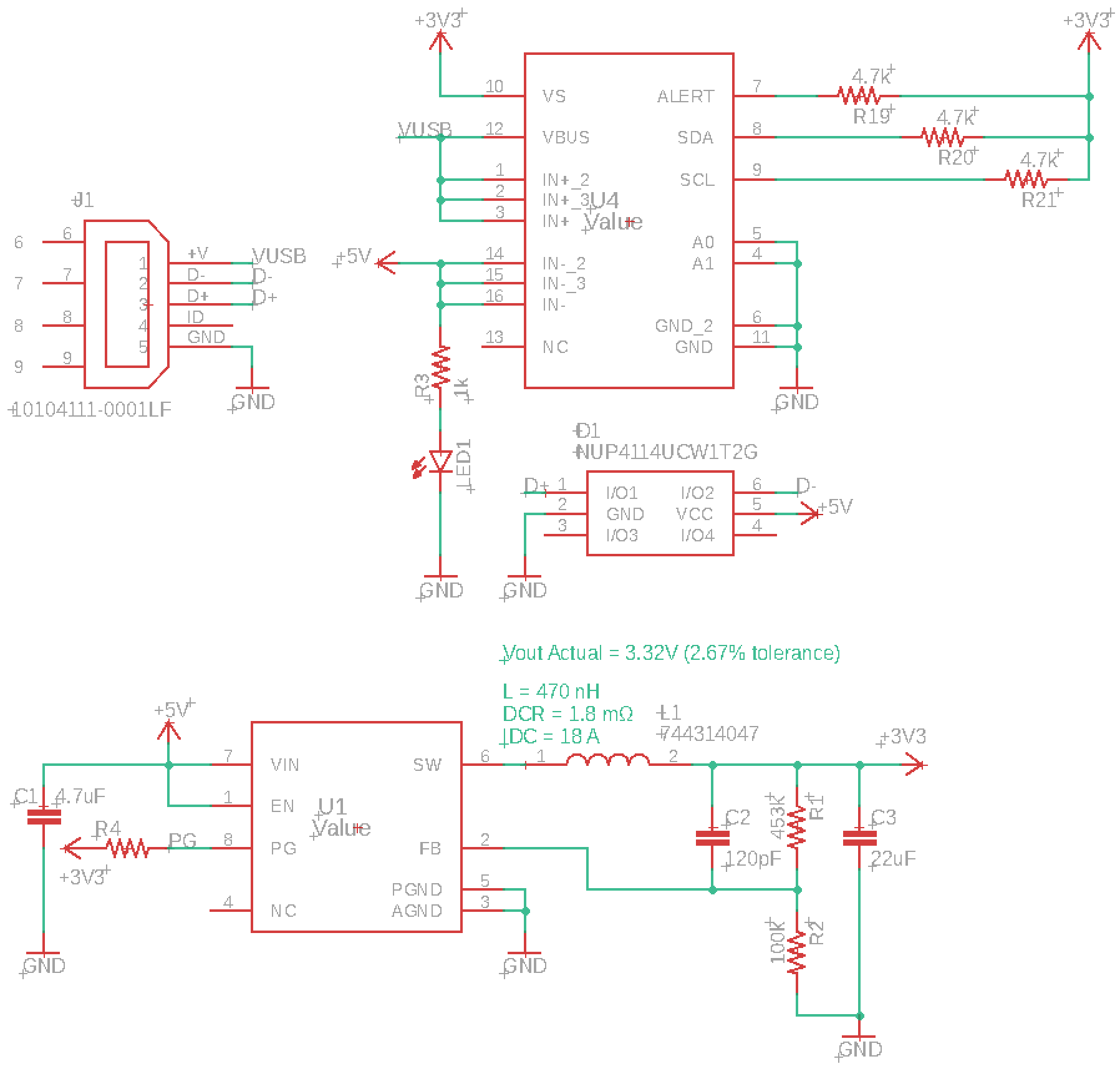
This will be connected to the buck converter and the TPS62821 (TPS62821DLCR) buck converter will power the CC3220SF Wi-Fi MCU.

I want to use the INA260 to see how many currents will be drawn.

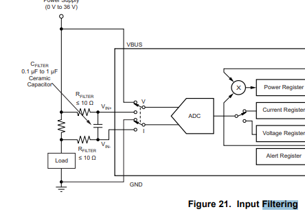
- Is this a correct way to track how many currents are driven from the micro USB?

- Since most micro USB can provide 0.5A current, can the INA260 handle this amount of current? I wish to know the maximum electrical characteristics, please.

  • Hi David,

    INA260 can measure 15A continuous current, so 0.5A current is no problem at all.

    The concern might instead be on the lower end of the current range. For example at 50mA load current, the measurement error will be 10% due to input referred current offset (5mA) alone.

    If better than 10% is required, you may want to consider a stand-alone shunt of bigger value. For example using a 0.1Ohm shunt will reduce the mentioned error by 50x when combined with a similarly specified current sense amplifier, such as INA226, INA233 or INA231.

    Regards, Guang

  • Thanks, Guang

    Guang Zhou said:
    If better than 10% is required, you may want to consider a stand-alone shunt of bigger value. For example using a 0.1Ohm shunt will reduce the mentioned error by 50x when combined with a similarly specified current sense amplifier, such as INA226, INA233 or INA231.

    Q0. Before closing, if I change to those chips, can I still use the aforementioned schematic to measure the current? I'm curious whether I need to change the above schematic.

    Hope you can check the RC input filter as well, please.

    Q1. For this case, what should I set for the MFR_CALIGRATION register?

  • Hi David,

    The schematic stays the same even if you decide to use discrete shunt + INA226/233/231, which is equivalent to INA260, only the shunt value is increased from 2mOhm to 100mOhm (or something else of your choice).

    Regards, Guang

  • Hello, Guang. I have updated my previous answer. Can you give me a feedback, please?

  • Hi David,

    R24 can be deleted and keep C32 only. Or have small R’s on both input pins as shown in the following diagram (from INA226 datasheet).

    Based on 100mOhm shunt and 1A max current, a current LSB of 100uA is a good choice, resulting in a calibration register value of decimal 512. With this selection, for the current range of 50mA to 500mA that you are expecting, the INA233 should return current values of D’500 and D’5000 respectively.

    A friendly reminder - don’t forget to assign A1/0.

    Regards, Guang

  • Thanks for your kind respond, Guang.

    Guang Zhou said:
    R24 can be deleted and keep C32 only. Or have small R’s on both input pins as shown in the following diagram (from INA226 datasheet).

    Got it. I removed R24.

    Guang Zhou said:
    A friendly reminder - don’t forget to assign A1/0.

    Thanks!

    However,

    Guang Zhou said:
    a current LSB of 100uA is a good choice, resulting in a calibration register value of decimal 512.

    Q0. I haven't understood this part; Do you mean, configure the MFR_CALIGRATION to 512 to use current LSB of 100uA?

    Q1.

    Guang Zhou said:
    for the current range of 50mA to 500mA that you are expecting, the INA233 should return current values of D’500 and D’5000 respectively.

    Actually, I wish to change the range to 1mA to 500mA. For this case, what else should change; the shunt resistor value, register configuration, etc?

  • Hi David,

    1mA to 500mA is a very wide range, in order to minimize error at 1mA, we’d have to choose the largest possible shunt value. With a 100mOhm shunt the offset will cause a max error of 10%. It can be slightly improved with a larger shunt however can only by so much before the shunt voltage is over the input range (82mV) at 0.5A.

    Yes 512 is the decimal value to program in to the MFR_CALIGRATION register. With this, the decimal reading corresponding to 1mA is 10.

    Other values can be chosen for MFR_CALIGRATION alternatively. For example you can set it to 2560. Then the decimal readings corresponding to 1mA and 500mA will be 50 and 25000 respectively.

    The determination of calibration register value is explained in section 7.5.2

    Regards, Guang

  • I see. Thanks, Guang

    A few more things before closing this.

    Guang Zhou said:
    1mA to 500mA is a very wide range, in order to minimize error at 1mA, we’d have to choose the largest possible shunt value.

    I see. In that case, I will use 100mOhm shunt with the range of 50 ~ 500mA.

    Q0. If I want a range of 50 ~ 500mA, do I have to configure certain registers of the INA260?

    Guang Zhou said:
    we’d have to choose the largest possible shunt value. With a 100mOhm shunt the offset will cause a max error of 10%.

    Q1. Is this 10% error in the datasheet? What is this error called? I can only find the 0.1% Gain Error.

    Guang Zhou said:
    t can be slightly improved with a larger shunt however can only by so much before the shunt voltage is over the input range (82mV) at 0.5A.

    Q2. I read from the datasheet that

    "IN+ and IN– can have a differential voltage between –40 V and 40 V."

    Can I ask what you've meant by "he shunt voltage is over the input range (82mV) at 0.5A"? I don't understand how you calculated that.

  • Hi David,

    Here are the answers to your questions:

    Q0 – there is not another register to program.

    Q1 – The 10% value is a rough estimate of the contribution of Vos. At 1mA load current, the shunt voltage is going to be 100uV developed across a 100oOhm shunt. Since the Vos spec is 10uV max, we should expect to see a max error of 10uV/100uV=10% from Vos alone.

    Q3 – The statement you quoted is referring to the fact that the device will survive under this condition. It doesn’t mean that the IC will work properly. The linear input range is defined in the spec table:


    We have some training videos that cover a wide range of topics related to current sensing. For example, here is one that talks specifically about how to size the shunt resistor.

    https://training.ti.com/getting-started-current-sense-amplifiers-session-4-how-choose-appropriate-shunt-resistor?cu=456802

    Regards, Guang