This thread has been locked.

If you have a related question, please click the "Ask a related question" button in the top right corner. The newly created question will be automatically linked to this question.

LMP8646: IC is not working in negative common mode

Part Number: LMP8646

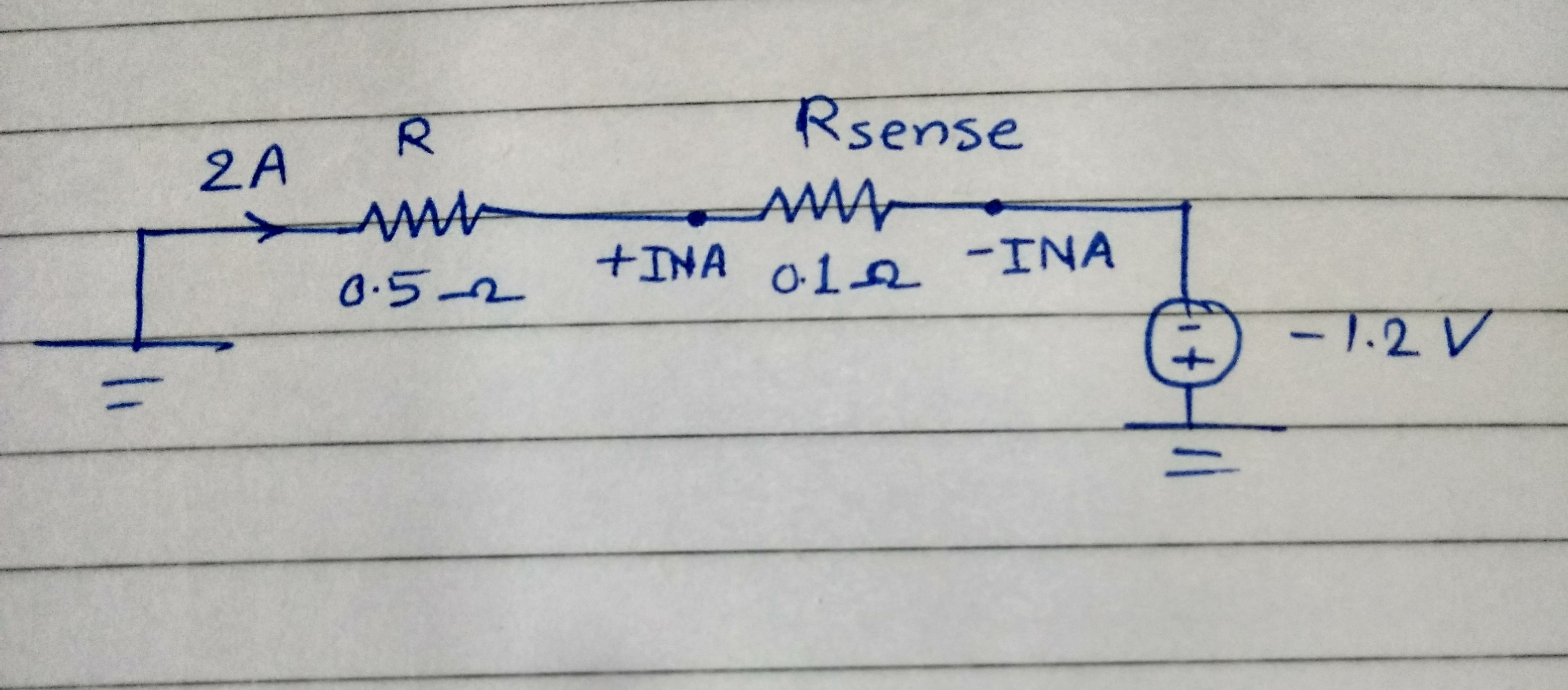
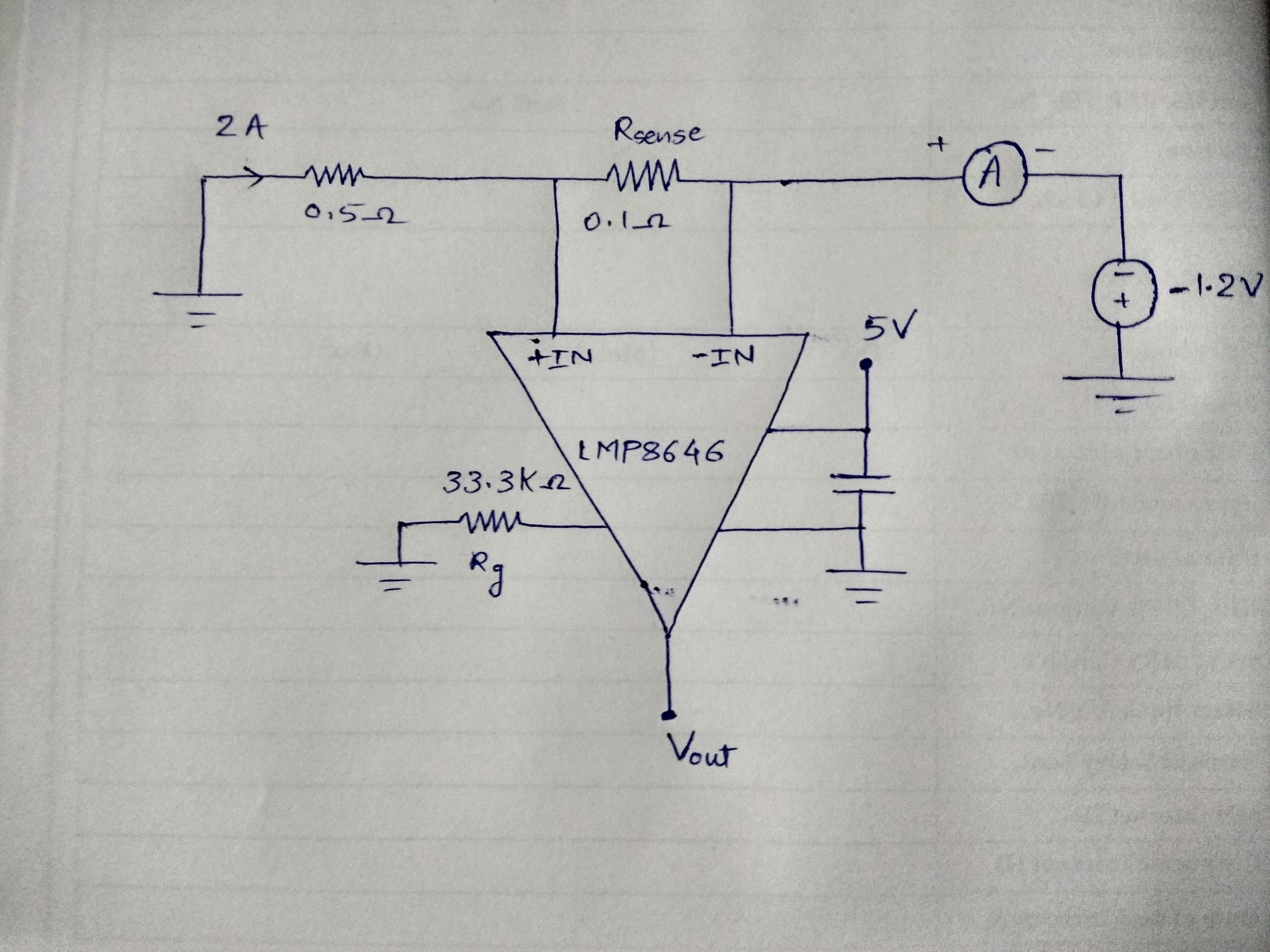
IC is not working in negative common mode voltage. It's working in positive common mode voltage  & when it is given negative common mode voltage its output voltage is not as per expectations.

After connecting the the negative common mode voltage the ic damages and don't work anymore.

The circuit on which I conducted the tests is given below.

  • Hello Manali,

    I apologize for the delay - our team was out of the office yesterday for a national holiday. One of our engineers is analyzing your question and will reply shortly. Thank you for your patience!

    Best regards,

    Ian Williams
    Applications Manager
    Current Sensing

  • Hello Manali,

    Thanks for coming to the forum!

    The LMP8646 should definitely work at your negative voltage rail and the polarity of inputs is correct. Could you provide some more schematic information: power supply, RG, output resistor, how everything is grounded, and test setup when you measure current for VCM >0V?

    This information can help me ensure I give you a fully informed response.

    Also, if you would briefly explain how you connect everything and turn it on then this would be very helpful too.

    Thanks,

    Peter Iliya

    Current Sensing Applications

  • The setup for positive and negative common mode voltage is exactly same except the polarities, they are reversed.

    Output voltage is measured using digital multimeter.

  • Hey Manali,

    When you say the polarities are reversed, do you mean the "-1.2V" turns into "1.2V". If so, then the amplifier is measuring a negative shunt voltage and this should not give a measurement since the device is uni-directional.

    How are you creating the -1.2V and 5V sources?

    When VCM >0, is VCM = 1.2V? Does this mean you switch the inpus of LMP8646?

    I am worried that you may be operating the device outside of recommended conditions. In section 7.3.1.1 of the datasheet, it states that for Case 1 if Vs >= 5V, the maximum possible output voltage of device is 1.3V. You are measuring 2A across 100mOhm and thus the VOUT = 2A*0.1Ohm*33.33k/5k = 1.3332V. This is beyond the maximum possible VOUT for this case. While this seems to conflict with your testing and VCM>0, I believe that the VOUTmax lessens as VCM becomes more negative.

    I would recommend trying to emulate the datasheet testing conditions and reduce the gain (Rg) so VOUT is less than 1.3V.

    Sincerely,

    Peter Iliya

  • Polarities are reversed in the sense IN+ is connected to positive voltage supply and IN- is connected to the load. Same as given in fig.26 of the datasheet.

    I have adjustable power supply which has 3 channels. One of them provides 0-30V and another one can provide negative voltage.

    I make the ground terminals common of both the power supplies before using and increased the voltages gradually after connecting the circuit.

    I tested the same circuit at 1A current as well for the same Rg. But it didn't work in either of the cases.

    If the maximum output voltage possible is 1.3V then how am I getting output voltage as 3 V in the case mentioned above.

  • Hey Manali,

    Ok so your are reversing the inputs when you reverse VCM polarity which is good because your load current is voltage-controlled by the bus voltage so it seems. Good.

    You are using a dual voltage supply and grounding all supplies to the COMMON of this dual supply. Good.

    1. Did you test measuring 1A with a potentially broken device or with a device that was just working when VCM>0 and never tested with negative VCM?
    2. When you were slowly adjusting the bus voltage (which slowly adjusts current), what was the device reporting right before it rails to 3V?
      1. With a proven non-damaged, new device, what happens when you slowly decrease the VCM from 0V to -1.2V for first time? Please note that a device may still provide valid measurements when VCM>0, but become non-operable when VCM<0V. This is because internal structures might have been broken during testing and will turn on with negative VCM, but will not turn on with positive VCM. To me, seeing the VOUT rail to 3V seems like device has been broken so please do not use this one when detailing the possible failure mode and mechanism.

    3. Can you confirm data for when device/test setup are working when VCM>0V? What are the measurements of VOUT and load current?

    Overall, I still cannot understand why it is breaking or not working, but having following data will go a long way here:

    • data when system works with VCM>0
    • data showing what VOUT does right before device stops working
    • data showing what VOUT does after a device potentially breaks
    • data should include load current, VBUS, IQ (device supply current), VOUT, RG
    • data for input bias currents (IB) before and after testing with negative VCM could directly show if device is breaking or not. So if IB goes out of specified limits after device is testing with negative VCM for the first time, then this could at least prove to us that this specific point in the test setup is breaking the device and then we can proceed from there.

    Best,

    Peter