This thread has been locked.
If you have a related question, please click the "Ask a related question" button in the top right corner. The newly created question will be automatically linked to this question.
Dear Tech Support
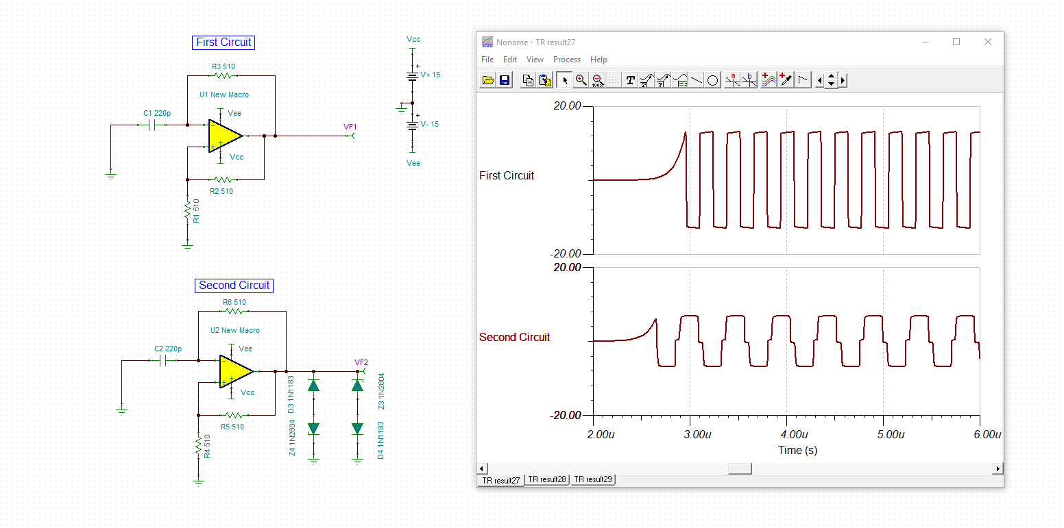
I am interested in using the LM7171 designed as a high frequency astable multivibrator, similar to the illustration shown in the data sheet. My question is: there are
no known values attributed to the diodes and zener diodes mounted across the output? Are these set to limit the output swing or, are they there to keep the signal on
the output locked to the zero baseline? How are the values of these diodes determined? Lastly, it seems that the output is a triangle wave at half supply level? Will I
need a second op amp such as, an LM7171 to function as a high frequency amplifier and a wave conversion to a square output with 50% duty cycle?
Regards
Michael
Cayote11@gmail.com
Hello Michael,
Having diodes and zener diodes mounted across the output of the multivibrator would indeed set the limit to the output swing depending on the zener voltage. In Figure 56 in the LM7171 datasheet, this is an example application circuit and the type of diodes chosen are dependent on your application. You could choose zener diodes with higher/lower zener voltages depending on your necessary output range. You could also use schottky diodes instead of the regular diodes or/and zener diodes if it is necessary to have a high switching speeds for high frequency applications; which seems to be for your case. I have attached a schematic of the figure if you would like to play around with the type of diodes available.
Thank you,
Sima
Hello Micheal,
Did Sima's response clarify your question?
Best,
Hasan Babiker
Hey Micheal,
I am going to close this thread due to inactivity. Please reply below or start a new thread if further support is needed.
Best,
Hasan Babiker