This thread has been locked.

If you have a related question, please click the "Ask a related question" button in the top right corner. The newly created question will be automatically linked to this question.

PGA308: What should I do if the input voltage signal is too large?

Part Number: PGA308
Other Parts Discussed in Thread: INA125, INA128, INA126

I checked the manual, the input voltage of pga308 is between 0.2V-3.6V. The sensor I use now outputs two signals, both of which are about 5V. I want to connect the output signal to the input of PGA308. What should I do?

  • Hi,

    you could use a voltage divider.

    Do you need the PGA308 at all, if your input signal is that large? Can you tell more about your sensor?

    Kai

  • Hi ,

    As Kai pointed out, you may use voltage divider. 

    Assume you are using Wheatstone bridge, you do not have to use equal resistors. You may use voltage dividers in Wheatstone bridge to reduce the output two signals to approx. 1.9V, if it is possible.  You are right, the common-mode input range of the PGA308 is between 0 and Vs-1.5V. 

    Please tell us more about you application so that we will give you best suggestions. 

    Best,

    Raymond

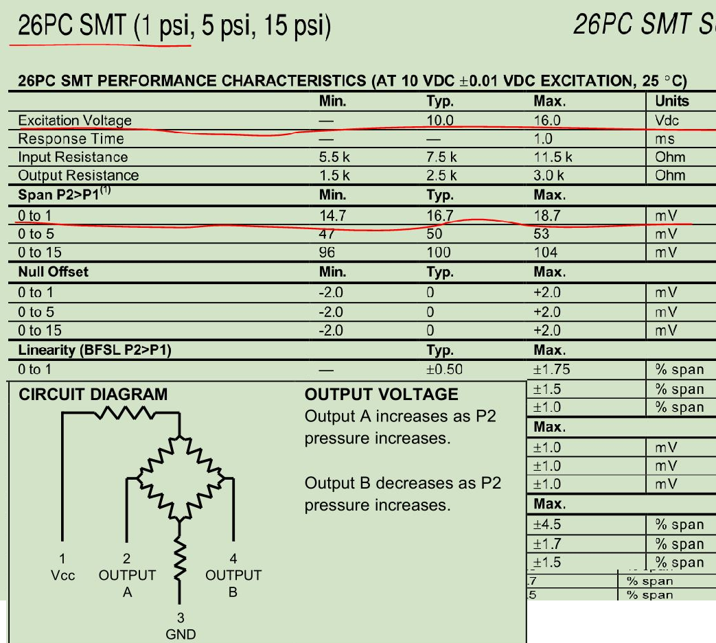
  • Thank you very much for your reply! I chose the 26PC01SMT pressure sensor to detect the liquid level. I want to use PGA308 to amplify the differential signal of the sensor.

  • Hi ,

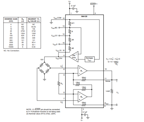
    26PC SMT pressure transducer is a single package Wheatstone bridge sensor, the output is fixed from the input excitation voltage, 10-16Vdc. You can not change the Wheatstone resistor network externally. I will suggest to use INA125 instrumentation Amplifier with the built in 10V precision voltage reference,  see the image below.

    http://www.ti.com/product/INA125

    If you have to use PGA308, you may first feed pressure transducer's output into one of INA126, INA128, IN129 instrumentation amplifier.  

    You may also use precision op amp buffer after the output of pressure transducer to reduce the voltage gain by half or perform another voltage divider to reduce the voltage. In theory, these methods are feasible, but the extra circuits are all going to introduce some kind of unwanted errors. And I do not recommended these, since this is pressure transducer, a fairly sensitive to these unwanted errors. 

    I am recommending the first option. When you invest in INA125, it comes with a precision voltage reference. And you can use single supply bridge amplifier configuration as well, see p.12 of the datasheet. Then you can connect to PGA308, A/D convert or MCU. You can perform the pressure calibration as well. 

    If you need further assistant, please let us know  

    Best,

    Raymond

  • Hi Raymond,

    If I use the  INA125, how can I debug to make the output zero when the Vi+ = Vi-? 

    Because the SX8725C was discontinued, so I wanted to find a chip to replace it, so I chose PGA308.

  • Hi Kai,

    thank you for your reply. I used the 26PC01SMT pressure sensor to detect the liquid level, because the SX8725C was discontinued, so I wanted to find a chip to replace it, so I chose PGA308.

  • Hi ,

    Question:

    If I use the  INA125, how can I debug to make the output zero when the Vi+ = Vi-? 

    Answer:

    I am fairly sure that the Honeywell's pressure transducer at the Wheatstone bridge's output is balanced, which V+ = V- with nominal pressure. The input offset voltage of INA125 is +/-50uV typical, +/-250 max.

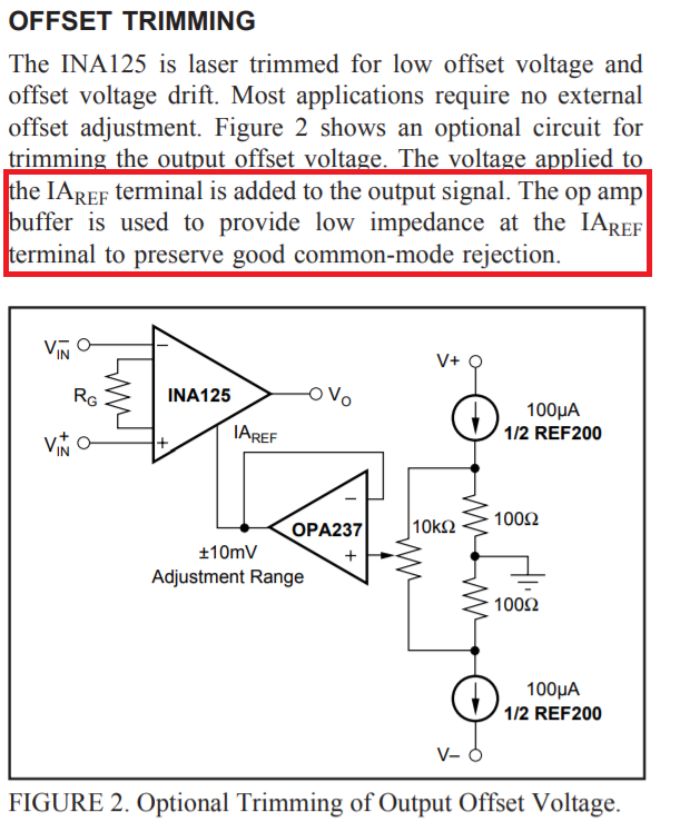
    The output of INA125's offset trimming can be adjusted at IAref or pin 5. However, you have to use low impedance voltage source or connected to ground, see the schematic on p.1 of the datasheet. The attached image is shown the optical trimming of output offset voltage with a unity buffer, where output of the buffer is a low impedance. IAref pin needs to connect to a stable low impedance voltage source against drift in temperature, noise or time. 

    Best,

    Raymond

  • Hi ,

    I forgot to mention that you can calibrate out any unwanted voltage and current offset errors through you A/D and MCU, if you want to have more precise measurement. Other errors such as temperature drift, nonlinearity and noise related errors are much smaller in INA125. 

    When the circuit is ready, you can place it in a known environment (temperature, pressure and humidity) and calibrated the entire sensor environment in the reference condition. This is the sensor calibration. 

    If the pressure transducer is perfectly balanced, you may short the input of Vin+ and Vin-, and calibrate out the INA125 and its remaining electronic errors. 

    Best,

    Raymond 

  • Thank you for answering my questions.