This thread has been locked.

If you have a related question, please click the "Ask a related question" button in the top right corner. The newly created question will be automatically linked to this question.

LM6172: Oscillations in output signal

Part Number: LM6172
Other Parts Discussed in Thread: TINA-TI, THS3092

Hi,

 I’m trying to amplify a signal after D/A application (0V -> 3V) with a gain of 3 (output signal: 0-> 9V): D/A > Non Inverting Amplifier.

Input signal is pulse with different time range: from 50 ns to 100ns.

My specifications are:

               • Power supply: -5/+15V or 0/15V

               • Dual channel if possible

               • BW of closed-loop: I want the RT faster as possible, for example 5ns, BW=0.35/5ns=70MHz


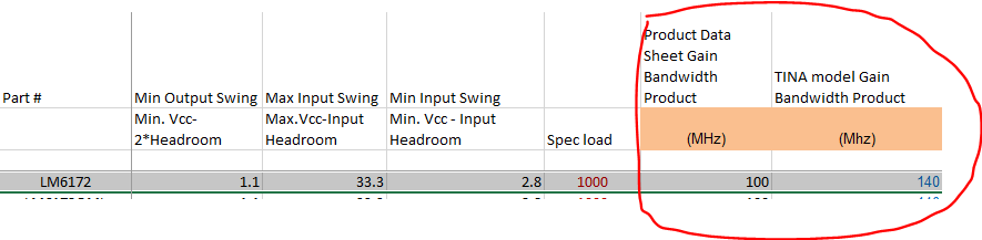
I found an opamp which is able to realize it : the LM6172, but when I simulate the behavior (on spice), I see some oscillations on the output channel.

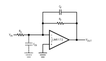
I designed an Non inverting Opamp with closed loop gain = 2 (R2/R1 = 2) => R2 = 20kOhm


Tried to reduce the resistor value (from 20kOhm to 20 Ohm..) in order to reduce the oscillations, it is working but the circuit consumption is too big: solution NOK.

I used a capacitor, but the value is very small (<2 pF), I’m doubtfull on it.

Maybe should I use the frequency compensation method.


My questions are:

  • Is the LM6172 a good choice for this application? If no, do you have other reference?
  • If yes, how can I reduce the feedback oscillations? or How to fix it? 
  • Is there another specification to add?


Thanks a lot.

Regards

Bob T.

  • Hi Bob,

    a feedback resistance of 20k is a bit too high. I would decrease it. How much decrease can you accept?

    What is the output load? Any output load capacitance there?

    Do you have a schematic? Or a TINA-TI simulation file?

    Kai

  • Hey Bob, the LM6172 VFA will not be fast enough at gain of 3, 

    You might want to go to a dual CFA device like the THS3092, if you are running non-inverting use the recommended Rf for gain of 3 for this current feedback device. You can tune the frequency response pretty easily on a CFA using the technique shown in figure 8 in this 1993 Comlinear original - later relabeled as a national app note, then later relabeded on the TI web site as SNOA366B where they removed this piece for some reason (likely did not understand it. This trick originally showed up in a design idea article by Howard Bandell, Harris Melbourne at the time. 

    OA-13CFA_LoopGain.pdf

    And yes, due to I/0 headroom requirements, you should use -5V and +15V supplies, 

  • Hi Kai, 

    Thank you for your reply. 

    I had moved on other subject, sorry. 

    For my application, I found a couple for feedback resistors: 1.74k/1k.  

    In order to decrease oscillations I would like to use a capacitor parallel to feedback resistor. I think this capacitor will cancel the pole in the opamp input, it's value is 1.2pF to 2 pF (see in datasheet page 16). I know the picture is an Inverting amplifier, but I will use the same philosophy with my no inverting VFA.

    What do you think about these values? Is the capacitor value so small? 

    The output load is a resistive load.And the input load is the DAC output (signal range from 0V to 3V). 

    I don't have Tina-Ti file because I used Spice simulation.

    As Michael said, maybe LM6172 isn't a good component for this application.

    Thank you for your help. 

    Bob

  • Hi Michael, 

    Thank you for your reply. I had moved on other subject, sorry. 

    I don't understand why a VFA isn't a good choice for this application? What is optimal gain value for LM6172 ? 

    I used your document, thank you, to determine the resistor value. I saw that my resistor values are to high for a non inverting application (17k and 10k), I reduced value at 1.7k and 1k, the output signal doesn't oscillate (due to the GBW) and the rise time is acceptable. That's why I don't understand why LM6172 will not be fast enough at gain of 3... I just want understand this part. 

    I read an other document you wrote, you speak about JFET amplifier.

    Maybe LM6172 isn't a good component for this application.

    Is JFET VFA an acceptable solution for my application? If yes, do you have a suggested reference? 

    Thank you for your help Michael. 

    Bob

  • These questions are a bit vague, any snapshot of a schematic would help. 

    way early on I saw a 70MHz target at gain of +3 - well, that suggests a 210 MHz GBP (approx). The LM6172 is far lower than that. 

    pretty much all AWG outputs use CFA to get the Full Power Bandwidth. 

  • Michael, 

    Thank you for your reply. 

    I understand why you wrote LM6172 isn't a good choice. 

    It looks like what I want, do you think is there an issue? 

    Thank you.

    Bob

  • Well Bob, if that 20nsec settling is adequate, looks good

  • I had this MFB design file open where the parameter database includes datasheet vs model gain bandwidth product, the LM6172 is 40% high in the model,