Hi,
I need to sense precision capacitance change of a resonant sensor. The signal is having bandwidth greater than 25 KHz. Hence standard CDC cannot help. I am planning to realize the sense circuitry with an opamp. Please help with the following.
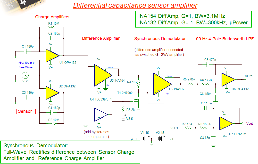
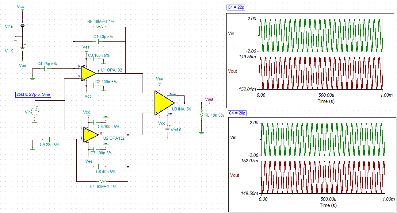
1) Which architecture is preferred viz Charge amplifier, TIA or Normal Buffer amplifier (Switched capacitor architecture is not selected)
2) Which parameter of the opamp is critical, the bias/offset current, voltage noise or current noise.
Any application note to throw light on above queries.
Thanks in advance
Karthik R