This thread has been locked.

If you have a related question, please click the "Ask a related question" button in the top right corner. The newly created question will be automatically linked to this question.

TLV6742: Two stage noise calculation

Part Number: TLV6742
Other Parts Discussed in Thread: TINA-TI, TLV9002, THS3491

Hi,

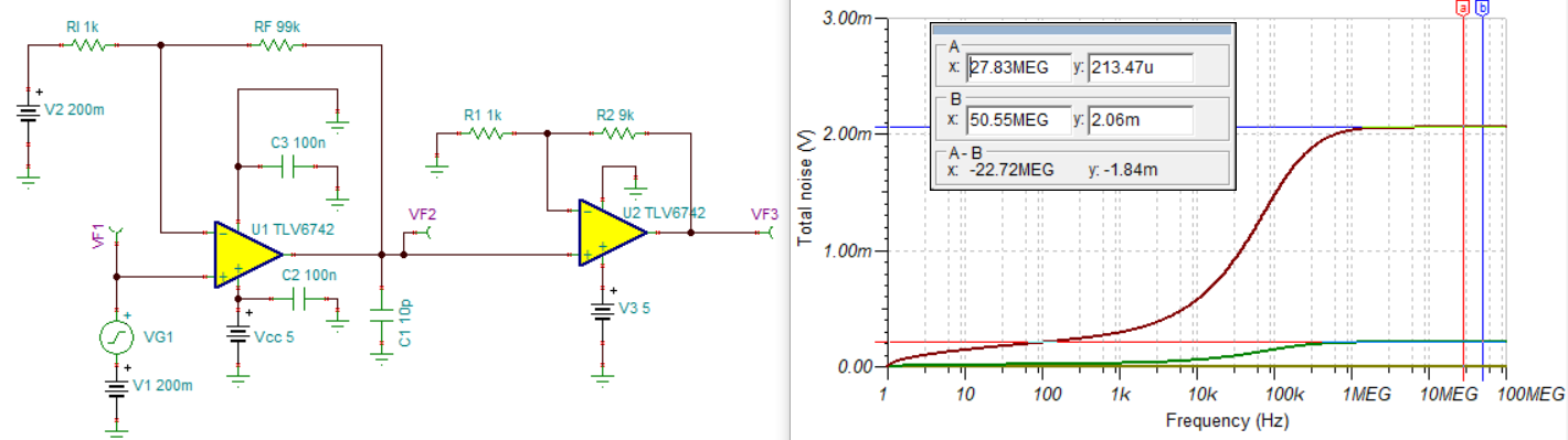
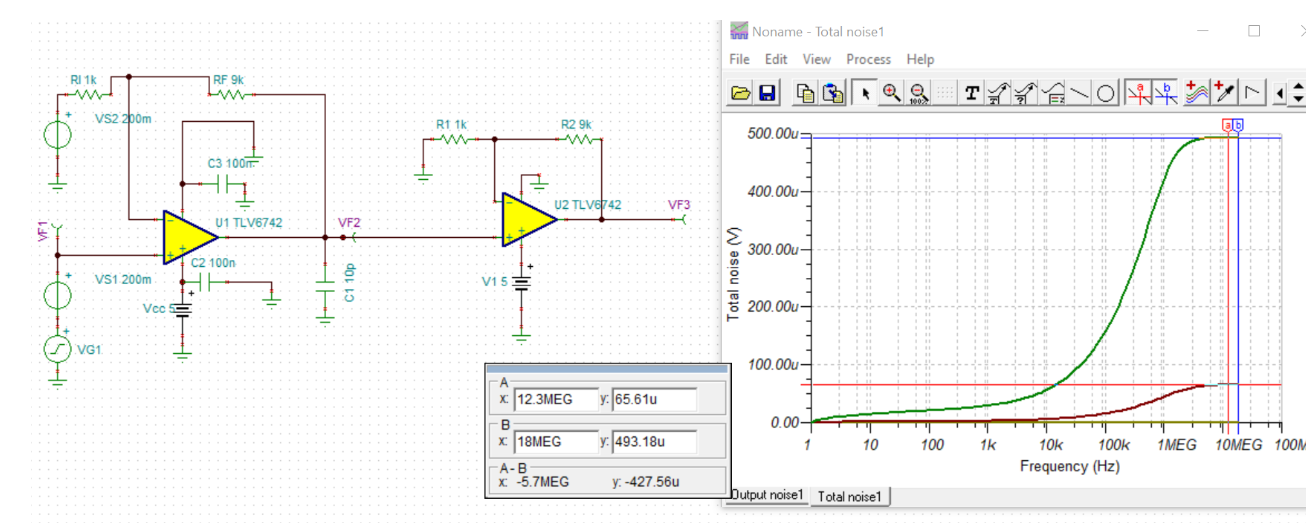
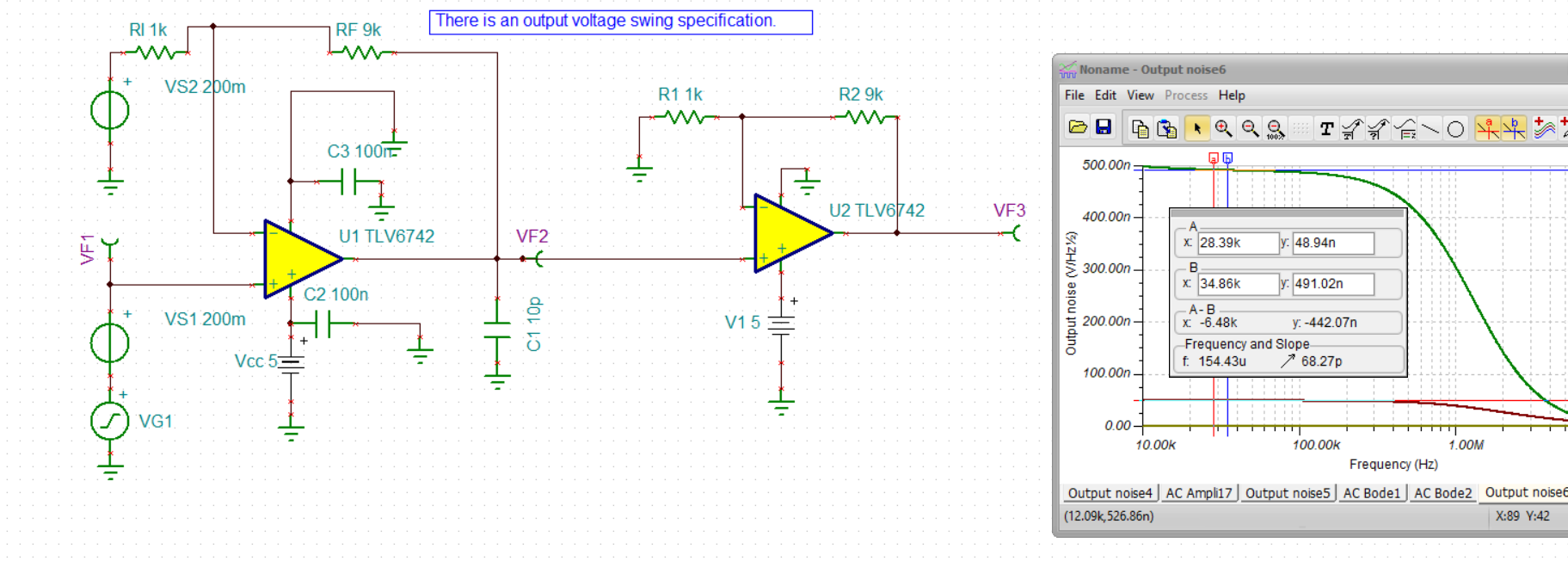
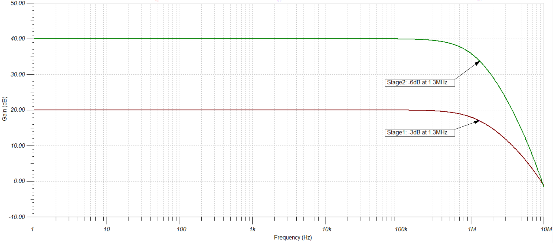
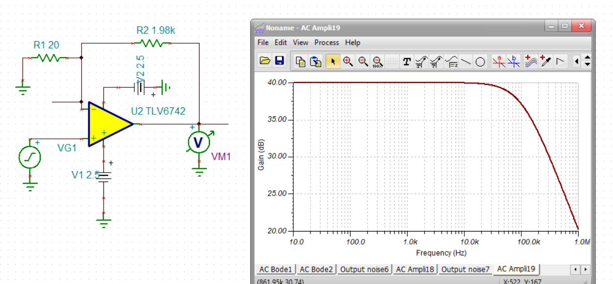
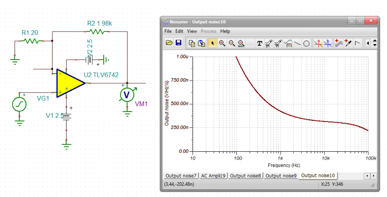
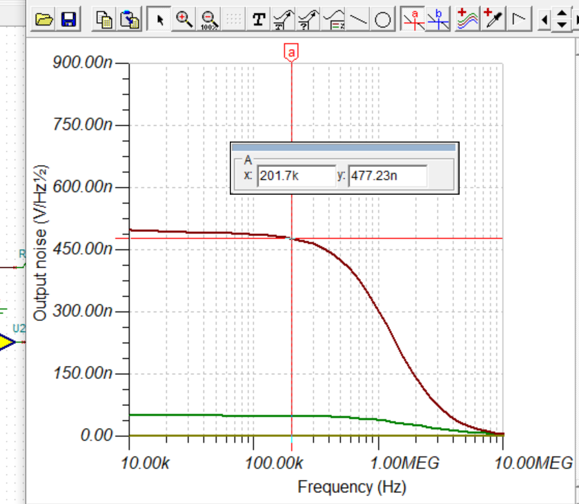
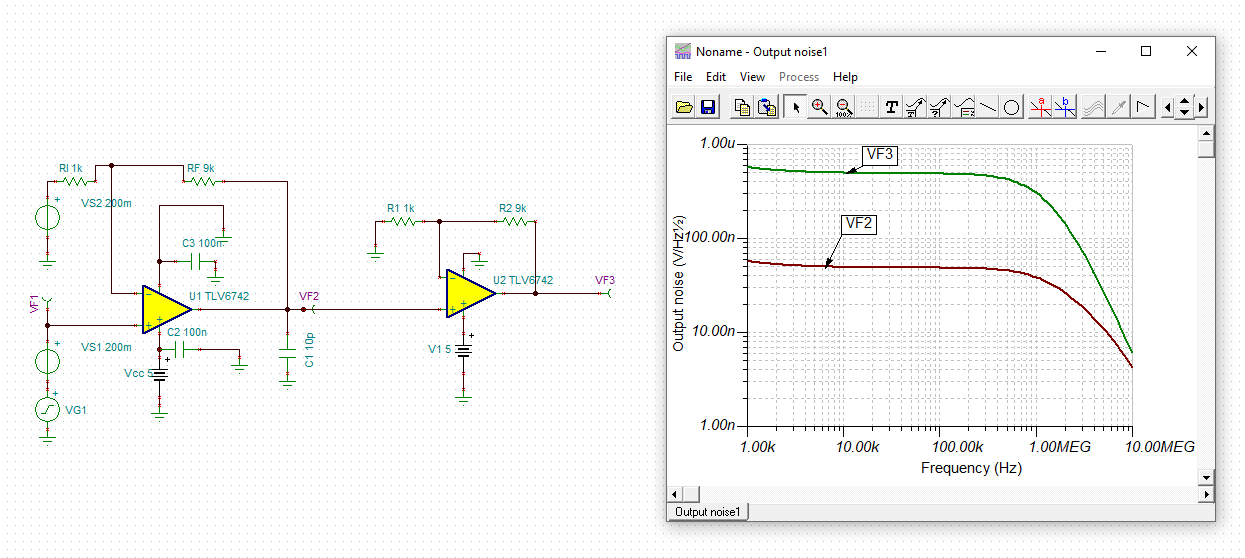
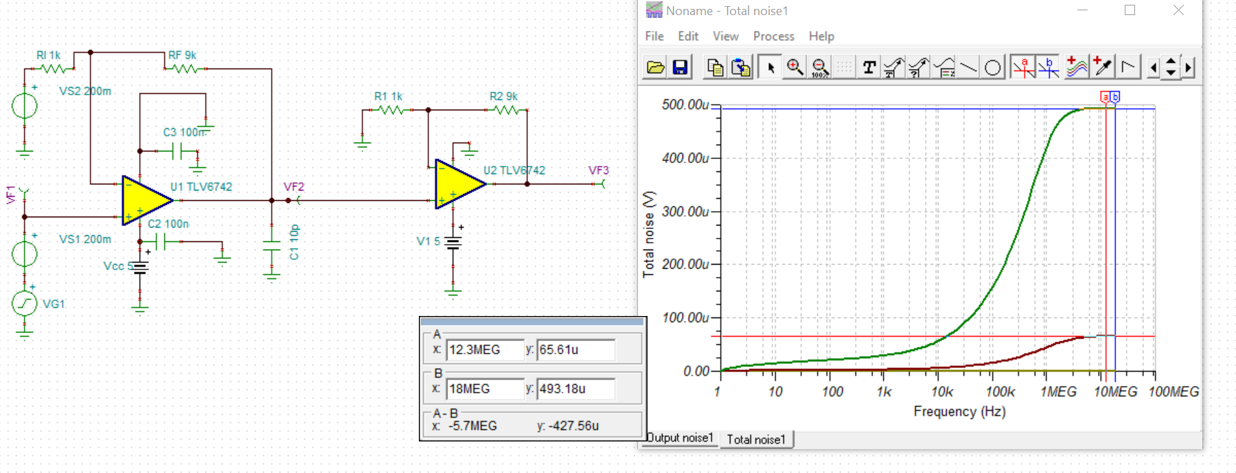
I have made a two stage amp simulation of TLV6742, and the gain is 10 each. The total noise of the first stage is 65uV rms, which is equal to the result of my calculation. However, the total noise of the two stage amp is about 493 uV rms, which is less than 65uV *10. 

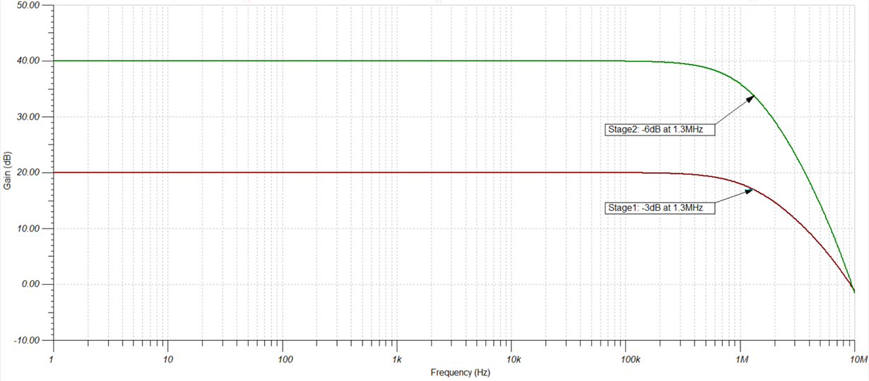
Is it because the second stage has the same bandwidth as the first stage, and the noise get reduced by the second stage? If so, how can I calculate the total noise of the two stage amp to get the result of 493 uV rms, like the simulation result? 

Thank you so much for your help and look forward to your reply.

Best regards,

Wendy

  • Former Member
    0 Former Member

    Hello Wendy,

    Thanks for your question.  It is a good question because according to TI Precision Labs the total overall noise should be about 10x the output noise of the first stage, assuming the bandwidth of both stages is the same and the noise of the first stage dominates the noise of the second stage.  This is the case here.

    I re-built your simulation in TINA-TI and got the same outputs.  I also re-did the hand calculation for the noise of the first stage and got an answer that was pretty close to the simulated value.  So, I do not think there is a mistake with the schematic and that the result for the first stage makes sense.  Also, I tried to use three different, 10MHz op amp models with three different model creators and, for every model, the output of the second stage did not have 10x the gain of the first stage.  So, I also do not think it is a model issue.

    If you increase the RF component value to 99k, you will have a first stage bandwidth that is 10x smaller than the bandwidth of the second stage.  In this case, the overall output noise is almost 10x the first stage's output noise as expected.  So, this suggests that it could be a bandwidth issue.

    That being said, I do not know how exactly to account for this.  I believe what is happening is that the noise of the first stage above the 1MHz region is being significantly cutoff by the bandwidth of the two stages.  In other words, it is like it is being attenuated by a second-order cutoff at 1MHz rather than just a first-order cutoff.

    I will try to dig into this some more and see if I can have a more exact answer for you.

    Regards,

    Daniel

  • Former Member
    0 Former Member

    Hi Wendy,

    Thanks for your patience.

    I am still working to understand this a bit better.  I have reached out to some colleagues for their opinion.  I will have an update for you within the next 2 days.

    Regards,

    Daniel

  • Hi Daniel,

    Great to know you. I also want to thank you for your great help.

    No problem! Looking forward to your reply.

    Best regards,

    Wendy

  • Hey guys, 

    I was looking at the 1st schematic - if that DC input is really 0.2V, should be sitting at 2V at the output of the 1st stage then clamping into the rails at the output of 2nd - check your DC operating points and maybe run spot noise sims at the output of each. 

  • oops sorry, I see that 0.2V bias on the Rg element now, 

    Can you put in the schematic in TINA file

  • Former Member
    0 Former Member in reply to Michael Steffes

    Hi Michael,

    Thanks for the help.  I'm a bit confused by your comment, "Can you put in the schematic in TINA file."

    Was this meant as a request?  I'm not sure I've understood here.

    Regards,

    Daniel

  • Hi Michael,

    Thank you for your help. To save your time, I have attached my TINA file here. Sorry I forgot this before.

    two stage.TSC

    Best regards,

    Wendy

  • Thanks Wendy, 

    yes, if you look at the output spot noise at low frequencies they are about a gain of 10 different as expected but the final output is rolling off early - that will look like lower integrated noise to the final output than expected. 

    Also, I notice looking at the data sheet an occasional error you see in the noise plot on the front page, that rolloff  at 30kHz is just the test set up probably at a high gain rolling off the output noise in test, not an input noise rolloff. I just put that comment in the next AudioXpress article - if you see an input spot noise rolloff, test artifact, not device input noise. 

  • I was also wondering if maybe they put that input voltage noise rolloff into the model, nope - flat at 3nV, too low in the model, but no rolloff, 

  • Former Member
    0 Former Member in reply to Wendy Wang1

    Hi Wendy,

    I think Michael's first point explains why the output noise is low.  If you look at the output noise for stage 1 and stage 2 after the 1/f frequency, at 10kHz for example, you’ll see that the stage 2 noise is 10x of the stage 1 noise just as expected.  However, the -3dB point for the noise comes about ½ of a decade earlier for stage 2 noise than for stage 1 noise.  So the overall output noise is lower than expected.  If you run a simple AC sweep, you’ll see the difference in the -3dB cutoff.

    I think this explains why the noise at the output of stage 2 is less than the (output noise of stage 1) x (gain of stage 2).

    Please let me know if you have any follow up questions.

    Regards,

    Daniel

  • Former Member
    0 Former Member in reply to Michael Steffes

    Hi Michael,

    Thanks for the insights here.  I think the lower noise can be explained, at least to an extent, based upon the earlier cutoff for the second stage.

    I had not run into the 30kHz roll-off before, but will be on the lookout for it now.  For example, it looks like the TLV9002 has the same behavior in the data sheet.  But again, the high-frequency roll-off is not included in the model.

    Thanks again,

    Daniel

  • Hi Daniel and Michael,

    Thank you so much for your help. I do have a question. Since two stages have the same GBW and the same gain, why the second stage has earlier cutoff? 

    Besides, I don't understand what's the meaning of "the rolloff at 30kHz is rolling off the output noise in test, not an input noise rolloff". Could you please explain it for me?

    Thank you again. Have a nice day!

    Best regards,

    Wendy

  • Former Member
    0 Former Member in reply to Wendy Wang1

    Hi Wendy,

    Both stages have the same cutoff.  It is just that the noise that is generated at the input of the first stage has to pass through both stages, so it effectively sees a higher-order low pass filter.  At the higher frequencies past the cutoff, the noise from the first stage will see about twice the attenuation when compared to the noise of the second stage.

    For Michael's second comment, I believe he is referring to the data sheet figure.  Because of the way the test is setup, it appears there is a roll-off in noise around 30kHz.  However, we would expect broadband portion of the curve to be flat as in the SPICE model.  I do not think it is something that you need to be concerned about.

    Regards,
    Daniel

  • Yes Daniel, I suspect the noise measurement was made at a gain of 100X, here is that sim for SSBW, 

    And then if you run the output spot noise at this gain of 100X you see about the right rolloff. This bandlimited noise was input referred by a fixed gain of 100X giving that slight rolloff above 30kHz, A few of the ADI datasheets make this mistake as well, 

  • Hi Daniel,

    I got it! Thank you so much for your patience and help!

    Best regards,

    Wendy

  • Former Member
    0 Former Member in reply to Michael Steffes

    Hi Michael,

    Understood.  Thank you, once again, for pointing this out.

    Regards,

    Daniel

  • Former Member
    0 Former Member in reply to Wendy Wang1

    Hello Wendy,

    I am happy to have helped and will now mark this thread as resolved.  Please reach out if you have any further questions.

    Regards,

    Daniel

  • Hi Daniel,

    Sorry, I suddenly got another question and it puzzles me.

    If we look at the output noise, we can see that the output noise of the second stage is rolling off early. But why?

    From the curve below, we can see that at about 200 kHz, the curve is flat and has little attenuation. Then why the output noise of the second stage begins to roll off at about 200 kHz?

    Thank you for your patience and support, as always.

    Best regards,

    Wendy

  • Hi Wendy,

    this has only to do with the linear scale of your output noise plot. When changing the linear scale to logarithmic scale the both curves will look similar and you see that the roll off at about 1MHz comes from the finite bandwidth of TLV6742 :-)

    Kai

  • Former Member
    0 Former Member in reply to kai klaas69

    Hi Kai,

    Good catch!  Thanks for the help.  Agreed, a drop of -3dB, or any other magnitude, at 40dB of gain will look greater on a linear scale than a similar drop at 20dB of gain on a linear scale.  The frequency response is more easily understood on the log-log plot.

    Regards,

    Daniel

  • Former Member
    0 Former Member in reply to Michael Steffes

    Hi Michael,

    Design was able to confirm for me that the early drop-off in the noise plot is just due to the gain of the test setup, as you predicted.

    Regards,

    Daniel

  • You bet Daniel, pretty common error - this will show up discussed in my October AudioXpress article using the THS3491 as an example - they were using 5kohm R's in some of the set ups, way bandlimiting the gains for the noise terms to the output - I think that led to a fit predicting 1.7nV input voltage noise, which is a bit lower than the device itself I suspect. 

  • And, my Sept AudioXpress issue showed up today with the 1st part of the noise measurement articles - this is the noise preamp discussion between the DUT and spectrum analyzer - at least the one we use in high speed, but generally suitable and quite a lot more sophisticated than a simple high gain op amp circuit. 

  • Hi Kai and Daniel,

    Thank you for the reply. I got it!

    However, when I try to calculate the output noise, may I regard it as a second order filter? But when I use the correction factor Kn=1.22, the calculation result of the output total noise is about 580 uV, which is still more than 500 uV. And it still can not match the simulation result of TINA. Even when I use the correction factor Kn=1, the calculation result of the total output noise is still more than 500 uV. Could you please help me with it?

    Really appreciate your help!

    Thanks & best regards,

    Wendy

  • Former Member
    0 Former Member in reply to Wendy Wang1

    Hi Wendy,

    I think it has something to do with the fact that the broadband noise in the model is about 3nV/rtHz while the datasheet specs something closer to 3.5nV/rtHz, as Michael pointed out before.

    If you look at the data sheet plot, it's does look like about 3nV/rtHz of broadband noise.  Either way, your hand calculations and simulation data will never match exactly.  But, it is a good practice to run the numbers by hand, as you have done, and ensure they are somewhat similar to your SPICE simulation results.

    Regards,

    Daniel

  • Hi Daniel,

    I got it! Thank you so much for your help.

    Best regards,

    Wendy

  • Former Member
    0 Former Member in reply to Wendy Wang1

    Hi Wendy,

    It is no problem.  I am happy we could resolve your issue.

    Regards,

    Daniel