This thread has been locked.

If you have a related question, please click the "Ask a related question" button in the top right corner. The newly created question will be automatically linked to this question.

OPA2335: How to determine negative supply voltage value

Part Number: OPA2335
Other Parts Discussed in Thread: OPA335

Hi Team,

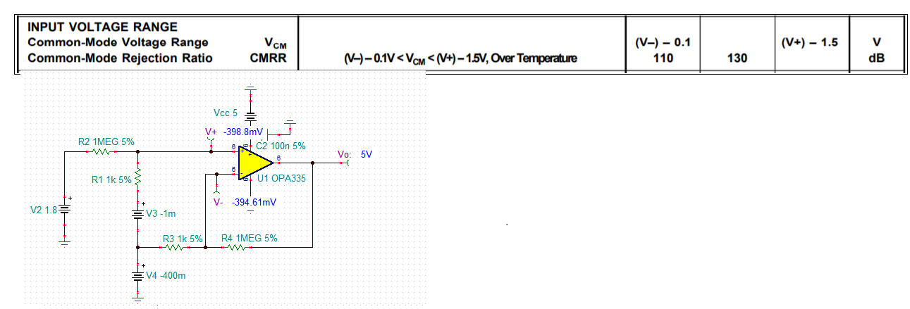
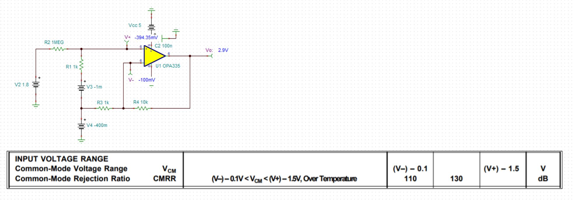
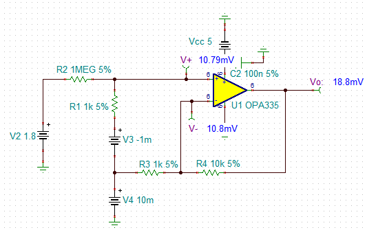
One question of OPA2335 from customer needs your support here. Below is the simulation illustration related with customer's real usage.

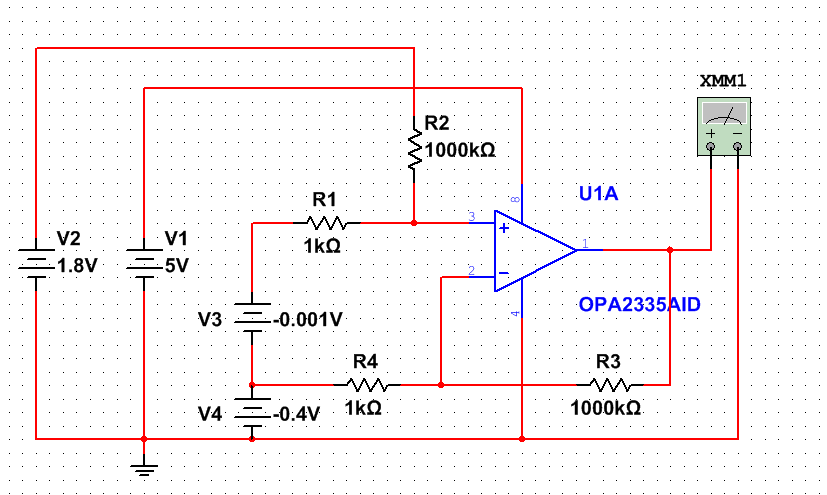
Under above circuit architecture, there is minor negative voltage V4(-0.5 ~ +0.5 Volt) in inverting input of OPA2335. V3(-10 ~ 10 mV) is the target sample voltage source. 

Here is a customer's question, how this V4 will influence sample accuracy of V3? If customer needs to add negative voltage supply in OPA2335, how to calculate this value? Calculation formula is welcomed.

Regards,

Stanley

  • Hi Stanley,

    because of the limited supply voltage range of OPA2335, this circuit cannot be handled by the OPA2335:

    stanley_opa2335.TSC

    I guess the gain of this circuit is too high.

    Kai

  • Hi Stanley,

    Thanks Kai for providing the simulation. 

    With 5Vdc single supply voltage, your input common mode voltage is limited to -100mV < Vcm < 3.5V for OPA335. The circuit below violates the input Vcm requirements. 

    /cfs-file/__key/communityserver-discussions-components-files/14/OPA2335-Vcm-08182020.TSC

    In addition, the circuit gain is too large as Kai pointed out (V3 is -1mV  shown in the circuit). However, you have to fix the DC bias first (Vcm) in order to have a proper linear output response. Currently, the circuit is not working properly. 

    You can derive the transfer function with superposition technique, if you want to analyze the circuit. 

    If you need further assistant, please let us know. 

    Best,

    Raymond

  • Hi Raymond,

    Thanks for your reply.

    Here is a strange thing when I try to lower the gain by changing R4 to 10kohm. The V- becomes -100mV, and the voltgae V+ is -394.35mV. But according to opamp model, V- should keep almost same with V+, right? What's the reasons behind this?

    The reason I ask above question is that the extreme Vcm of OPA2335 will influence the negative voltage supply value customer should choose.

    Regards,

    Stanley

  • Hi Stanley,

    V- should keep almost same with V+, right? What's the reasons behind this?

    The OPA335's input common mode voltage is limited to -100mV < Vcm < 3.5V. The circuit's V- =  -100mV, V+ = -394mV, which it does not comply with Vcm requirements. 

    When input Vcm voltage ranges are outside of the OPA335's requirements, the output will not behave linearly. Therefore, V+ and V- will not track (because of the output does not have the linear response). 

    If you have other questions, please let us know.

    Best,

    Raymond

  • Hi Stanley,

    better use the ideal OPAmp to see what's going on:

    Later, you can optimize your OPA2335 circuit :-)

    Kai