This thread has been locked.

If you have a related question, please click the "Ask a related question" button in the top right corner. The newly created question will be automatically linked to this question.

INA333: output has large ripple

Part Number: INA333

Hi,

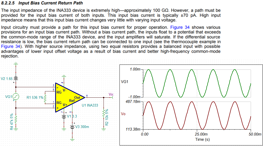
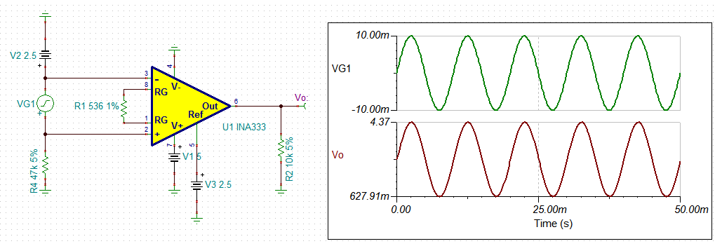
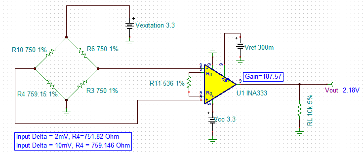
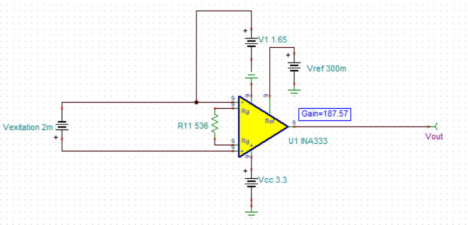
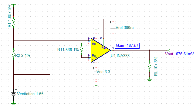
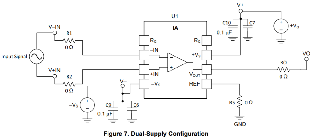
I'm using INAEVM-MSOP8 to test INA333 with below configuration. V+=3.3V, V- = 0V. REF=0.3V(not to GND shown in the picture), IN- to GND is 1.65V(add a 1.65V reference from IN- to GND), RG=536ohm, which sets GAIN=187.

when 2mV is added to IN+ to IN-, the output waveform is 

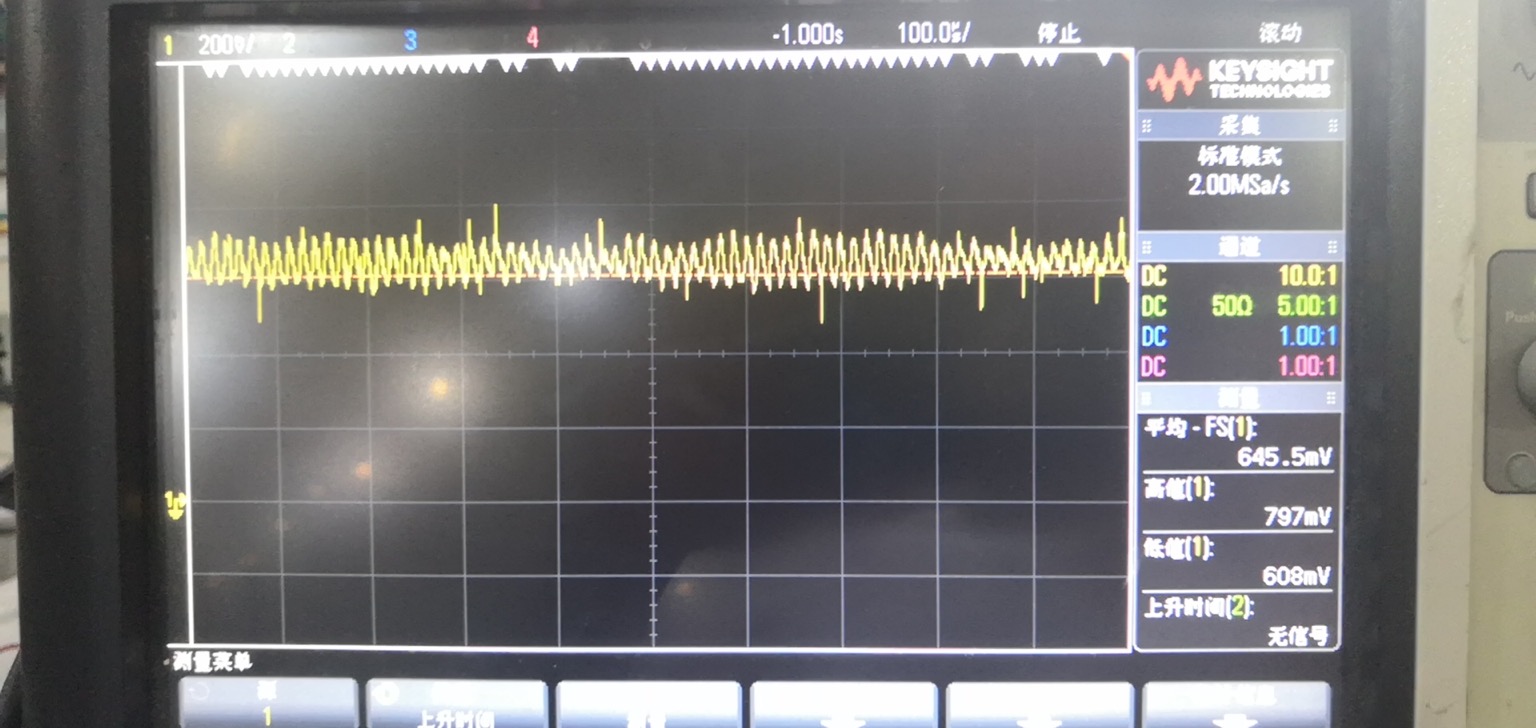
when 10mV is applied to IN+ to IN-, the output waveform is

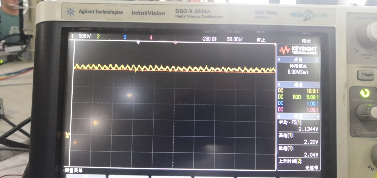
We are sure the power supply, the REF pin is very stable. 

So why is there output ripple(about 190mV)?

  • Hi Howard,

    Two issues may result your problem. 

    1. One is the input bias current return path, which may be missing.

    2. Your Vref is too low for the input voltage. 

    Since your gain is 187.57, the 1mV delta at input of INA333 will generate 187.57mV swing at output. With Vref=0.3V and Vin+ - Vin- = 1mV, the output swing is shown in the image below. With 2mV delta at input, your output is going to swing below ground, which is one problem. 

    with 10mV delta across the input of INA333, your output swing will be 1.8757V. Even Vref is configured at mid rail of 3.3V, your output is going to swing below ground. You may have to use +5V as the single supply rail or reduce the input delta signal or reduce the gain. 

    /cfs-file/__key/communityserver-discussions-components-files/14/INA333-Ib-Re-Path-8242020.TSC

    If you have other questions, please let us know. 

    Best,

    Raymond

  • Raymond,

    the input is DC 2mV and 10mV, not AC, so we expect the output to be DC also.

    And 1.65V is applied from IN- to GND, so we think there is input bias current return path.

    The 2mV or 10mV signal is generated from a pressure sensor, and the output impedance of the sensor is around 750ohm.

  • Hi Howard,

    Please verify if you have the following circuit. If not, please provide me with the actual schematic. 

    /cfs-file/__key/communityserver-discussions-components-files/14/INA333-Pressure-Transducer-08242020.TSC

    Best,

    Raymond

  • Raymond,

    the circuit is as below:

    No load is connected to output, and 1.65V bias is connected from GND to IN-, the input signal 2mV is generated by a DC source, not a real pressure sensor.

  • Hi Howard,

    increase Ro to 100...470R.

    Kai

  • Hi Howard,

    What type of 2mV power supply are you using? Switcher or linear power source. I have a feeling that INA333 is measuring the power supply's noise and ripple at the same time + 2 mVdc. The CMMR is high for INA333, but if the test setup is connected as shown in the above configuration, 2mV and 10mV input's noise are not rejecting, because the ripple noise is not common. 

    In your second example with 190mV output ripple. If I assumed that the circuit is gaining 187X, the input ripple of 10mVdc will have at least 190mV/187 =1.013mV of ripple on top of DC, which is not unreasonable. 

    Please try the following circuit to rule out the issues. Change R2 to 2 and 10 Ohm, and observe the INA333's output. 

    In addition, I have several follow up questions. 

    1. What is the ripple frequency from the scope shot? It is hard to tell from the screen capture.

    2. What is scope's BW? Can you limit the scope's BW to 20MHz, and measure it again. 

    3. I think that Kai's suggestion to place 100 to 470 Ohm in series with Vout --> to filter out the noise at the output when you perform the scope measurement. 

    Best,

    Raymond 

  • Hi Raymond,

    according to my simulation the INA333 becomes instable with a capacitive load of 1nF (-> scope AND digital voltmeter connected to the output of INA333 at the same time). Anyway, it's a good idea to have an isolation resistor at the output of INA333.

    Kai

  • Hi Kai,

    Yes, it is good to know. I did not check on the stability. Let us see what are the findings from the customer. 

    thanks,

    Raymond