This thread has been locked.

If you have a related question, please click the "Ask a related question" button in the top right corner. The newly created question will be automatically linked to this question.

LMP7715: Potentiostat circuit: Negative Output in reference electrode? is that possible with an op amp with unipolar input voltage?

Part Number: LMP7715
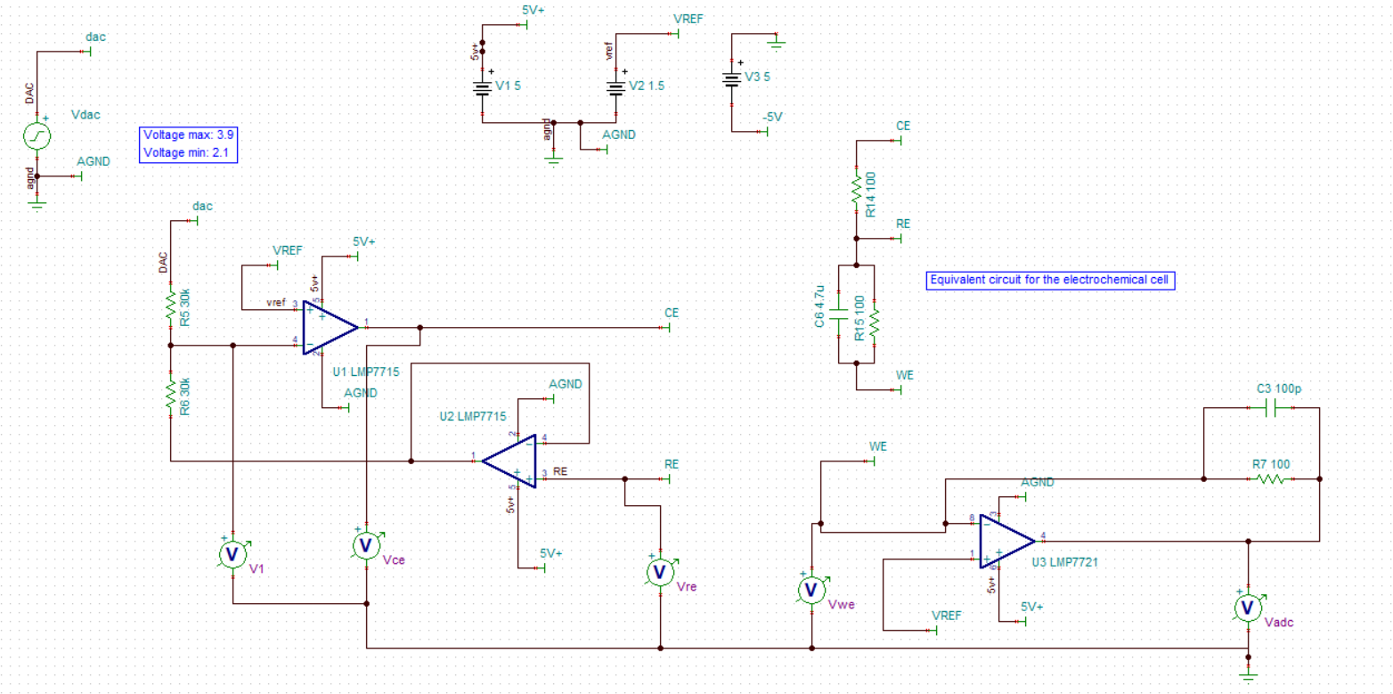
I saw many potentiostat circuits on the internet that use these OP AMPS with unipolar power and claim to have negative drive voltages at the reference electrode. My question is if this is possible with unipolar supply voltage? I understand that this cannot be possible or am I wrong?
According to my numbers, (Vwe-Vre) / 100 = (Vre-Vce) / 100, so Vce = 2Vre-Vw, where Vwe = Vref = 1.5 -> Vce = 2 * Vre-1.5 Also, (Vdac-Vref) / 30k = (Vre-Vref) 30k, where Vre = 2 * Vref-Vdac -> Vre = 3-Vdac Finally, Vce = 2 * (2 * Vref-Vdac) -1.5 -> Vce = 4.5-2 * Vdac;
So I want to have voltages between -900mV and 900mV at the reference electrode, so the DAC would oscillate between 3.9V and 2.1V. this is correct? or I misunderstand the operation of the circuit? But is it possible that these op amps, with unipolar power supply, can give those negative voltages? I thought not, please help me.

  • Hi 6366576,

    Q: My question is if this is possible with unipolar supply voltage? I understand that this cannot be possible or am I wrong?

    If I understood your questions correctly, you want to make 3-electrode chemical cell or potential static instruments. Here is the reasons why this is not possible. 

    3-electrode chemical cells consist of Working Electrode (WE), Reference Electrode (Ref) and Counter Electrode (CE) or sometimes it is referring to electrochemical potentialstat or Galvanostat. 

    Reference electrode is a chemical electrode, typically it is made of AgCl, AgNO3 etc.. Reference electrode is chemical redox reference for chemical reduction and oxidation to take place. The reference's chemical potential does not change (has to be chemically stable). Your voltage from -0.9V to 0.9V refers to chemical potentials from Vwe with respect to Vref. This is high impedance measurement between the Vref and Vwe electrodes (floating measurement). I recalled that if Vwe - Vref is set positive with respect to reference electrode, the working electrode is performing electrochemical reduction (electron is flowing into the WE electrode). If Vwe- Vref is set negative, the electrons are flowing away from the working electrode, which the WE is performing electrochemical oxidation (It has been a long time, I believed that the electrochemical redox convention is correct).  

    Counter electrode (CE) is typically used as stable metal, like Pt, Pd, Ni, Stainless Steel, Ag or other relevant electrodes depending on the chemical reactions that  is taken place in a three-electrode cell. The CE is used to source or sink current in the electrochemical system. Therefore, you have to use bipolar power voltage source or power op amplifier to generate the source or sink current to perform the chemical redox reaction.

    Working electrode (WE) is the measurement interest electrode. When electrons are injected into the electrode, it is doing electrochemical reduction. When electrons are extracted from the WE electrodes, it is doing electrochemical oxidation. The entire 3-electrode cells are immersed in aqueous or non-aqueous (organic) ionic salt solution. In addition, there is a potentiostat in scan or sweep rate in from uV-mV/sec that electrons can be injected and/or extracted at a specific rate, say from -0.9V to 0.9V at 10mV/sec.  

    Enclosed are some links that I found over our website, which including the application note of PH electrode measurement. PH electrode application is a low current application measurement, which is used to measure the PH of aqueous solution. The high current potentiostat measurement can source or sink current  from +/-3A to +/-10A or even higher. Regardless of the system's current rating, the basic building blocks are very similar. 

    Please let us know your max. current and voltage application requirements, we can recommend something for you. In any events, you will need high precision, low offset, low drift, low leakage current, high input impedance op amps to handle the application.   

    https://www.ti.com/lit/ds/symlink/lmp91002.pdf?ts=1600814157903&ref_url=https%253A%252F%252Fwww.ti.com%252Fsitesearch%252Fdocs%252Funiversalsearch.tsp%253FsearchTerm%253Dpotentiostat%2Bapplication%2Bnote

    https://www.ti.com/lit/an/snoa529a/snoa529a.pdf?ts=1600814645698&ref_url=https%253A%252F%252Fwww.ti.com%252Fsitesearch%252Fdocs%252Funiversalsearch.tsp%253FsearchTerm%253Dph%2Belectrode%2Bapplication%2Bnote

    www.membrapor.ch/.../Application_Note_MEM1.pdf

    https://e2e.ti.com/support/amplifiers/f/14/t/608831?keyMatch=POTENTIOSTAT%20CIRCUITS&tisearch=Search-EN-everything

    Best,

    Raymond

  • Raymond, thank you so much for the great explanation. It helped me a lot.
  • Hello E2E user,

    I'm not sure if you're looking for any more information regarding this circuit or not... but I was reviewing a potentiostat circuit for a different application and came across this so I thought I'd chip in.  Raymond covered electrodes in much further depth that I will (or can!), but I thought I'd just chip in from the circuit standpoint. 

    Amplifier U3 is configured as a transimpedance amp (TIA).  It's common mode is set to Vref.  Vref is 1.5V.  The two inputs of the op-amp are at the same potential, so WE is by definition at 1.5V.  The output of the TIA will be 1.5V - i*100 (R7).  

    Now let's look at U1.  Its common mode is also set to 1.5V (Vref).  So the difference between DAC and Vref divided by 30k (R5) generates a current.  That current cannot enter the high input impedance op-amp, and therefore flows across R6 (also 30k).  Since U2 is in a buffer config, the input (RE) is at the same potential as the output.  Therefore RE teeter-totters (inverts) around 1.5V.  aka if DAC is at 2V, RE will be at 1V; if DAC is 1.75V, RE will be 1.25V.  It's a little inverting amplifier.

    Now for the CE terminal.  The output of U1 will be whatever it needs to be (hence the power of negative feedback) to regulate RE to the desired voltage.  Essentially CE will be the current thru the cell * 100ohms (R14).  But that's not you're worry, this Kelvin connection takes care of itself as long as you don't rail an amplifier.

    So YES, you can apply + and - differential voltages across the cell with this circuit with single supply.  It is due to the shifted non-zero common mode voltages of the amplifiers used.  As a colleague here would say, "ground is a fictional point is space" so you can call Vref ground and ground a negative voltage if it makes you feel better haha!

    Hopefully that helps.