Other Parts Discussed in Thread: TIPD126
Hey,
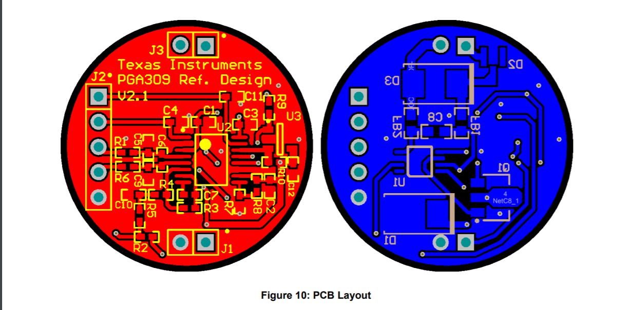
I am using XTR117 in transmitter product by referring TI's CerTIfied design TIPD126.
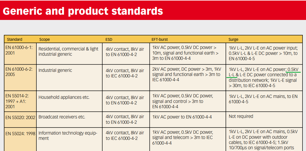
We have used same component as shown in the TI's design but we were failing the surge immunity test. After the failing at 500V surge we tried using two SMBJ40CA (TVS diode) in parallel this helped us pass the 500V test but still we weren't able to pass the 1KV or 2KV test. The diode is failing short, protecting the XTR117 and rest of the circuitry. We are working with 24V DC input. We are using XTR117's internal voltage regulator to generate 5V and external LDO for the 3.3V rail.
We are not sure what is going wrong.
Our schematic 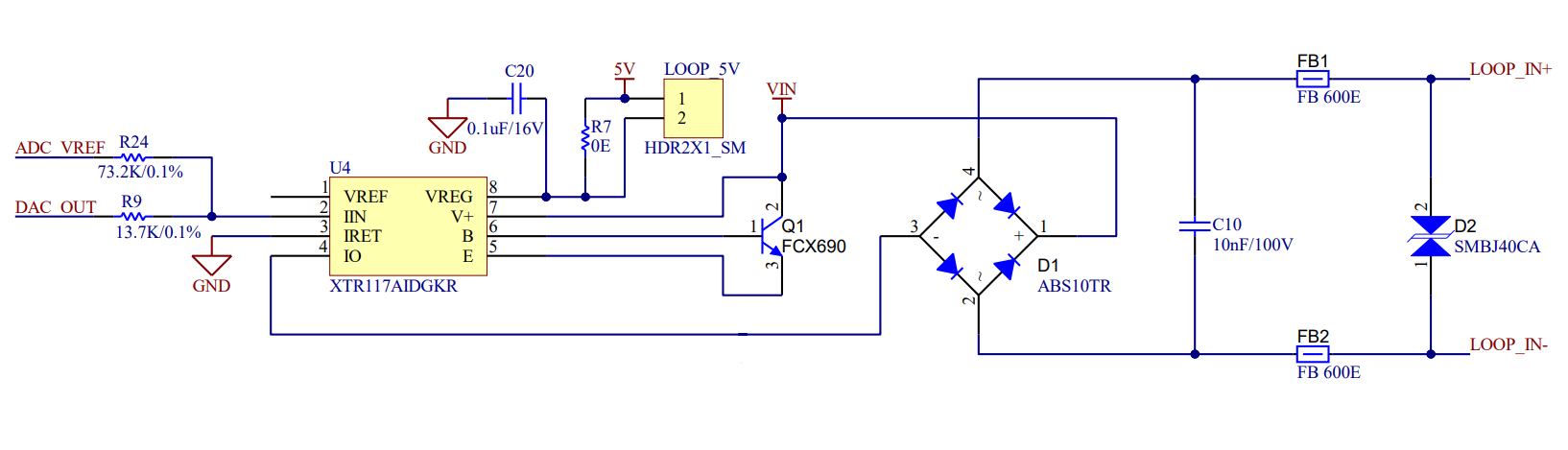
TI's Schematic