This thread has been locked.

If you have a related question, please click the "Ask a related question" button in the top right corner. The newly created question will be automatically linked to this question.

LM258: internal two amplifier interference in single supply operation

Part Number: LM258
Other Parts Discussed in Thread: LM358B

Hi team

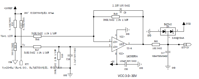
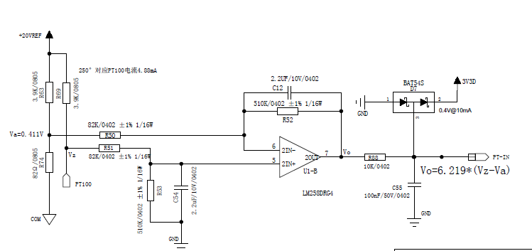
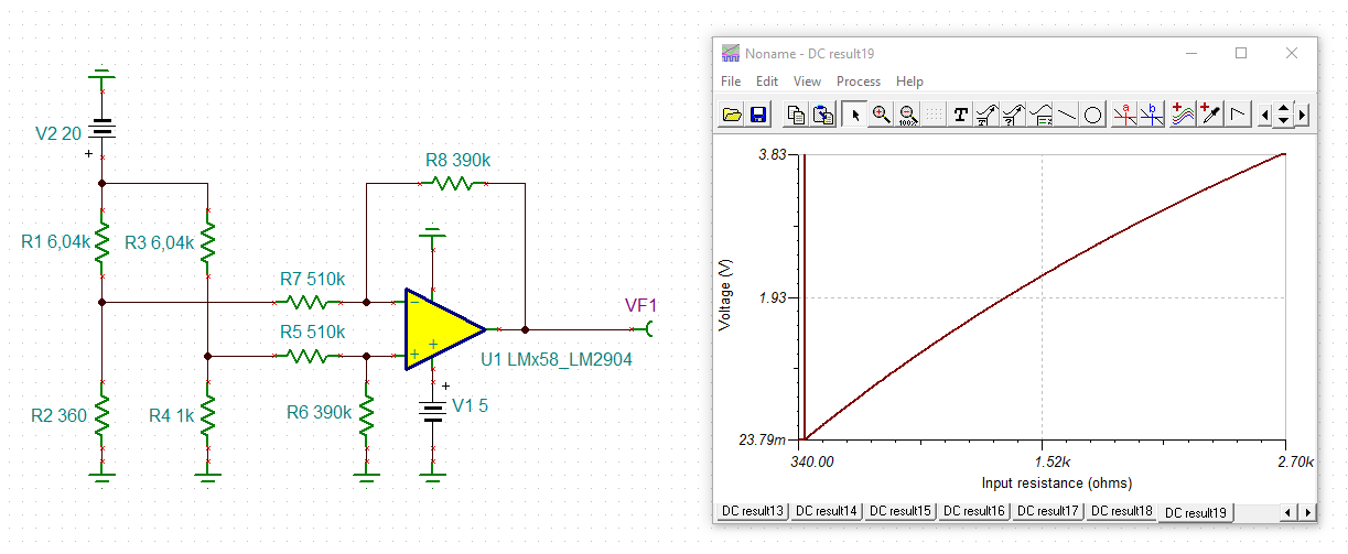
Here customer use LM258 for two temperature sensing, but found these two temperature sensing circuit would interfere each other when using signle supply operation. However with postive/negative supply, the two internal ampifier works fine. 

Customer tried LM358B, same interactions  happened when using single power supply.  I am wondering what impact/difference would brought to customer board with single and positive/negative supply?

Based on the schematic, is anything unreasonable need to be modified? 

  • How exactly do they interfere with each other?  What are the changes made with a bipolar supply?

    The LM258's common-mode range goes only up to V+ – 2 V, which is 3 V in the circuit above. What are the maximum desired input and output voltages? Does the bipolar supply use a higher V+?

    What is the load that +20VREF can handle? Do Va and Vb stay constant?

  • Hi Gene,

    apart from issues at very low and very high temperatures, the circuit should work well. (The caps omitted for simplicity in this plain DC analysis, but needed for AC stability!):

    gene_lm258.TSC

    Kai

  • Hi Gene,

    Clemens asked a very good question. How are these two circuits influencing each other? Is there an increase in offset voltage when one output changes? Please be specific.

    I noticed there is a PT100 net label in the schematic, does the 100 ohm resistor connect directly to this node? Similarly, does the KIY net label in the first circuit have a PT100 connected to it? 

    A possible cause of this issue is PCB layout causing the input common mode voltage to go below GND due to differences in GND potential. I noticed there are two different GND symbols (COM and GND). This may be causing the input common mode voltage to go below ground if the two different grounds are at a potential.

    Thank you,

    Tim Claycomb

  • Hi Tim

    Appreciate for your help! I asked customer to try higher power supply or lower Vin+/-, it works fine. Just one quick question, is these two ampfier inside the chip independant? If one channel input exceed the common mode voltage range, would another channel normal operation be affected?

    Best Regards

    Gene

  • As long as you stay inside the recommended operating conditions, they are independent.

    The two amplifiers share the power supply. If one inputs goes too much negative, a current will flow out of GND, which can affect the rest of the chip. See Design Guidelines for Devices with LM324/LM358 Cores for details of the internal circuits.

  • Hi Gene,

    Clemens is correct. They are independent as far as Vcm, Vout swing, Vos, etc. is concerned. However, if you turn on the ESD diodes both amplifiers will be effected because they share a power supply.

    Thank you,

    Tim Claycomb