This thread has been locked.

If you have a related question, please click the "Ask a related question" button in the top right corner. The newly created question will be automatically linked to this question.

LMH6628QML-SP: The output voltage swing when the device is supplied with V+=+5V and V- = GND

Part Number: LMH6628QML-SP
Other Parts Discussed in Thread: TINA-TI, LMH6628, LM98640QML-SP

Hi Team, 

According to the datasheet of LMH6628QML-SP, the device is capable of a typical output swing of ±3.8V from a supply voltage of ±5V. Our customer wants to know the output voltage swing when the device is supplied with V+=+5V and V- = GND. 

Regards,

Danilo

  • Hi Danilo,

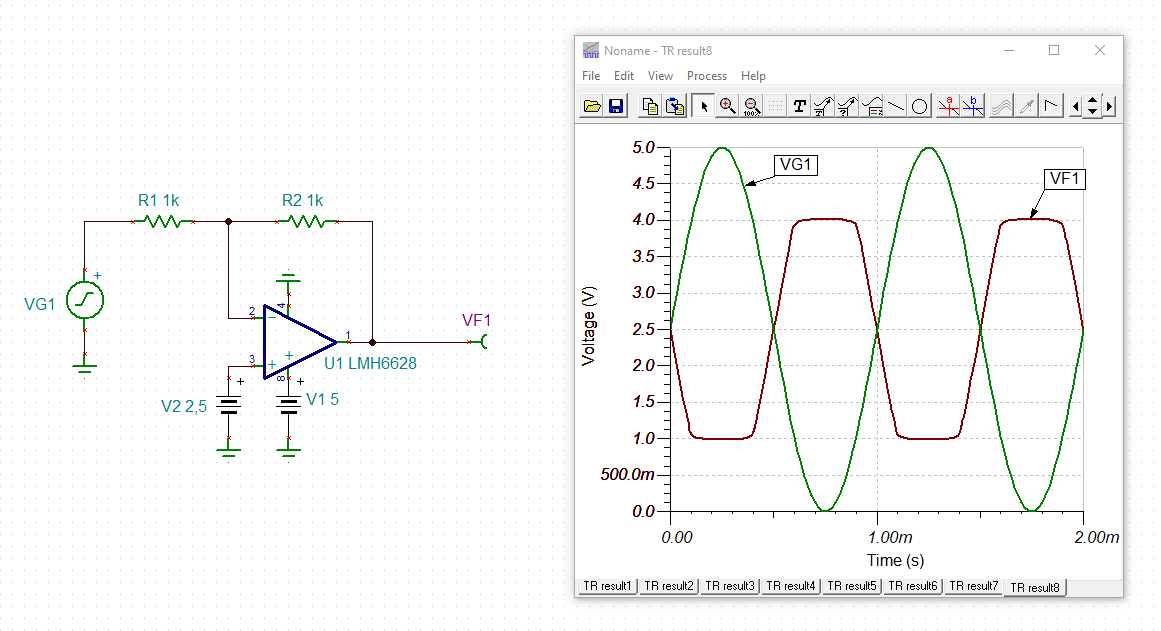
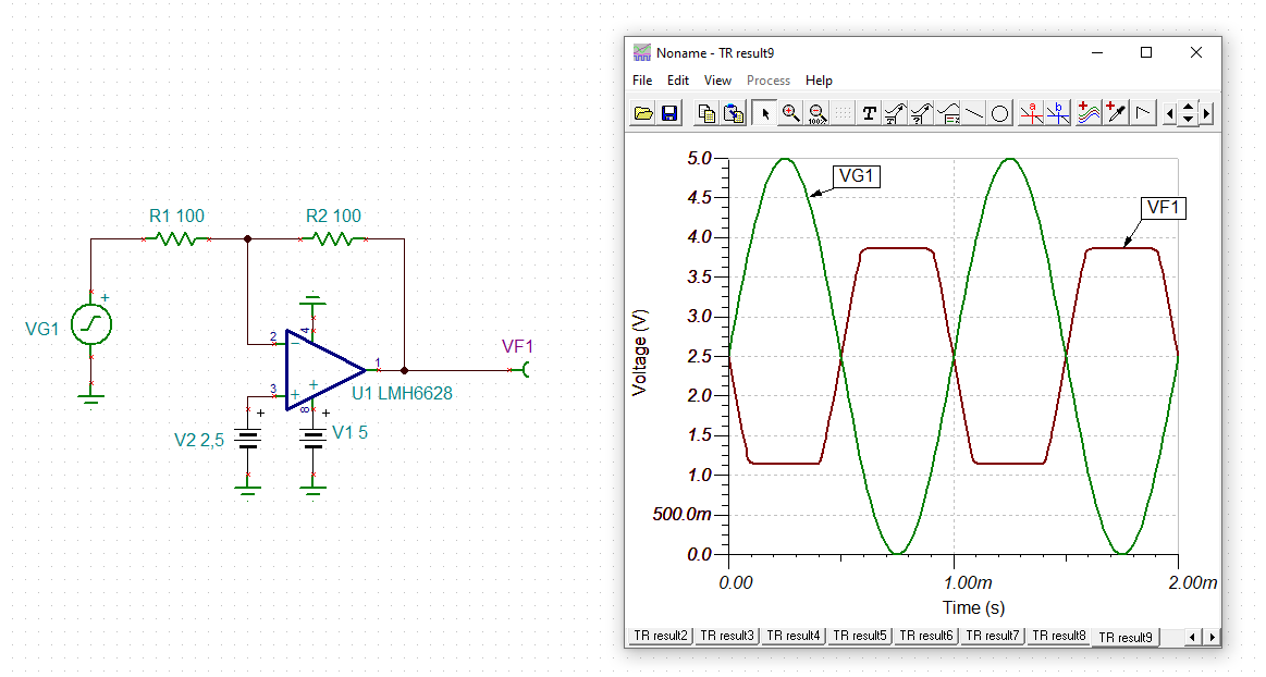
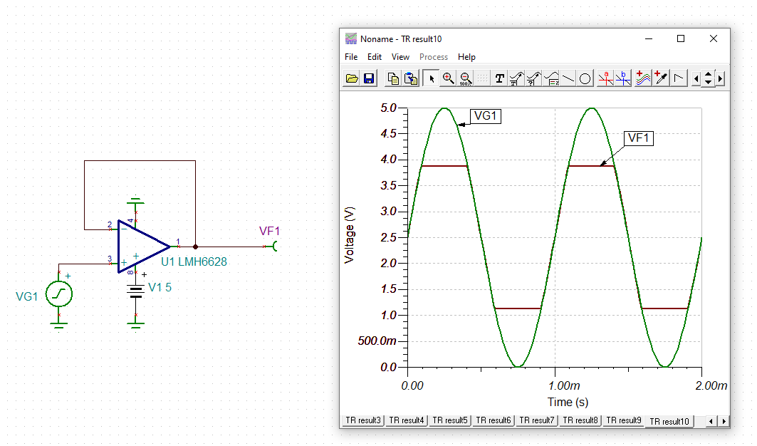
    that's what the TINA-TI simulation is showing:

    danilo_lmh6628.TSC

    Keep in mind that the common mode input voltage range of LMH6628 is limited as well:

    Not sure whether the model properly works at these low supply voltage values. And, in any case, what you see here are only typicals. Let's see what the TI's experts are saying :-)

    Kai

  • Hello Danilo,

    We don't have any measured data with a +5V supply, however the results from sim as Kai highlighted should give a good approximation. 

    Best,

    Hasan Babiker

  • Hello All,

    Thank you Danilo, Kai and Hasan for your answers. I am at the root of this question.

    However, I would like to use the LMH6628QML-SP for my design and having a good approximation with simulation for a space grade component is not enough to convince my customer.

    In order to give you more context : I would like to use this amp op for a preconditioning stage between a camera with voltage range between 1.4V and 3.8V and the LM98640QML-SP analog front end.

    Do you know how I could reduce the risk on the output swing ? Do you know if the LMH6628QML-SP has the same die that the LMH6628 (and manufactured in the same way and at the same place ?).

    Kind regards,

    Thibaut 

  • Hello Thibaut,

    I will look into your question in regards to the die & manufacturing further, but I do believe that the performance for both devices will match closely. 

    Keeping that in mind, it should be noted that the output swing of +/-3.8V under a +/-5V supply assumes a no load condition and is also the typical case. Figure 25 of the datasheet should give you a better idea of your output swing once a load is introduced. Note that the load resistance here seem to be the overall load which takes the feedback resistor into account as well. I would say the best way to maximize your output swing would be to try and limit the output current of the device, either by increasing your feedback resistor or by introducing isolation resistance at your output.

    Best,

    Hasan Babiker 

  • Hello Thibaut,

    I can't share any info in regards to the die & the manufacturing sites, however the performance of the devices should be similar. In regards to the main question, the output headroom isn't a spec that varies much with various supply conditions (as long as you are within the operating range of the device). You should expect around the same +3.8V output condition for a +5V supply at a no load condition.

    Best,

    Hasan Babiker