https://www.ti.com/lit/ug/slau502/slau502.pdf AN web link attached here.
------------------------------------------------------------------------------------------------
Hi expert,
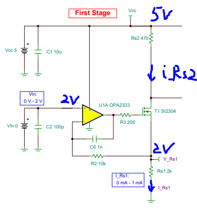
If we only look at the first-stage current sink generator of this circuit.
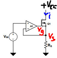
Vs across Rs will generate negative feedback to amp A1, but if Vs <VIN the amp A1 will directly go into saturation to output around Vcc(if rail 2 rail).
My questions are as below:
①If VIN<Vcc, due to negative feedback adjustment, Vs=VIN might be the final result, A1 is in linear state.
In below figure, i_Rs1=i_Rs2, marked as i. Consequently i=VIN/Rs=2V/2k=1mA, than Vds(Q1)+V(Rs2)=Vcc-VIN=3V.
Thus, Vds(Q1)=3-470*1m=2.53V, Q1 must be in linear area, right?
②If VIN>Vcc, Vs<VIN as always, then A1 output is saturated, Vg=Vcc.
Vgs=Vg-Vs, Vds(Q1)=Vcc-Vs, i=Vs/Rs.
Q1 must be in linear-area state to balance Vgs, Vds and i relationship. So if VIN>Vcc , it is also okay for this design, right?