This thread has been locked.

If you have a related question, please click the "Ask a related question" button in the top right corner. The newly created question will be automatically linked to this question.

LMC6064: LMC6064IN

Part Number: LMC6064
Other Parts Discussed in Thread: LMP7721, LMP91000

Hello, 

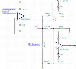
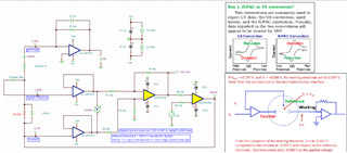
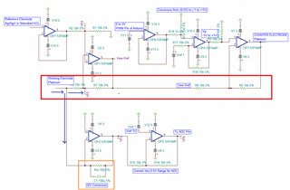
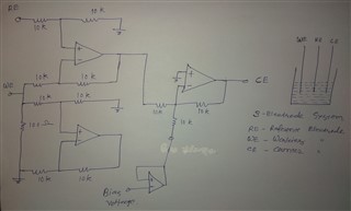
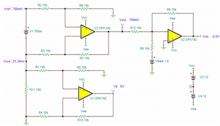
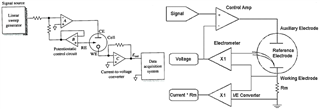
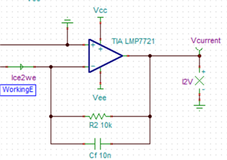
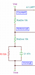
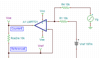
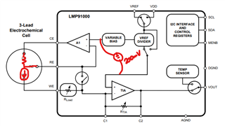
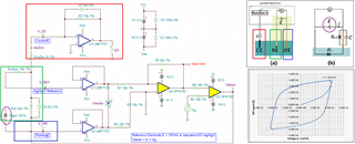
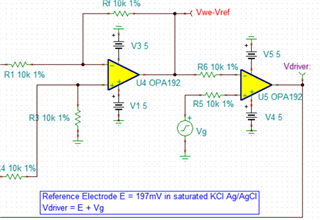
I have developed op-amp circuit for three electrode system as shown in attached image.

In this, I want to apply bias voltage between WE (Working electrode) and RE(Reference Electrode). All three electrodes are kept together in electrochemical cell.

In testing, I have applied 1.8V as bias voltage but no any current flow found through CE(Counter Electrode). 

Actually, current should be flow through CE. Please suggest.

  • Hi Director :-)

    can you explain how the circuit shall work?

    Also, what is the supply voltage of LMC6064?

    Kai

  • Hi,

    Indeed as Kai said, we would need further explanation about how your design works to be able to better assist you.

    There are a number of well established op based potentiostat/galvanostat circuits seen on line that work as intended. Here is an Applications Report from TI, AN-1798:

    https://www.ti.com/lit/an/snoa514c/snoa514c.pdf

    Another nice Application Report from a another source:

    https://www.ecochemie.nl/download/Applicationnotes/Autolab_Application_Note_EC08.pdf

    Regards, Thomas

    Precision Amplifiers Applications Engineering

  • Hi Director CSMCRI,

    Here is the simulation of potentiostat circuit, which is not working. 

    I did not use the proper op amp for the cyclic voltammetry application, but you are able to check out the simulation model.

    OPA192 Potentiostat 03152021.TSC

    Below is the captured potentiostatic image from a link that Thom is suggested. The CE electrode should source the voltage (positive or negative), chemical RE electrode is referenced to a WE electrode, and electrons should be injected or extracted from the WE electrode for a redox chemical reaction. 

    In the image below, WE electrode is configured as Transient Impedance Amplifier (TIA); and measured current or electrons to WE is converted from current to Voltage and output as voltage vs.RE based on redox reaction.  

    CE is a voltage source to drive the required current between CE to WE electrodes based on the RE electrode.and controlled signal at CE eletrode. RE electrode or potential is referenced to WE electrode. Both CE and WE electrodes are required to source or sink voltage and current. 

    I do not have your potentiostat requirements. LMP7721/LMC6064 op amps may or may not work for your application. It has the current sensitivity and ultra low bias current and high input impedance, but it does not voltage amplitude (LMP7721 op amp) to drive the redox reaction, unless your application about pH or similar low current and low voltage electrochemical reaction. For high current and voltage redox application, you may use LMP7721/LMC6064 op amp at the front end of electrochemical interface, but additional power amplifiers or power supply are required to drive heavier load in a three electrochemical cell.  

    If you need further assistant, please let us know. 

    Best,

    Raymond

  • Hello Raymond,

    Earlier, I have Used OPA228P Op amps in circuit and I can use it in current circuit. The explanation given by you is exact what I want to do. But I am not sure about the design which I have prepared. I have also tested the simulated circuit provided by you and found out that it is not working. Will you please suggest that what design changes should I opted to get the exact output.

    Thanks

  • Hello Thomas Kuehi,

    I have gone through both reports provided by you. I have design the circuit for same application mention in reports but I did not found the output. I want some suggestion on circuit. design 

  • The circuit should work exactly as cyclic voltammetry (Three electrode system). The potential between working electrode and reference electrode must be constant and counter electrode will work as voltage source for WE & RE. The current (source or sink) will flow through counter electrode and working electrode. 

    The supply voltage of LMC6064 is +/- 5V.

    Basically I need support on circuit design.

  • Hi Director CSMCRI,

    Could you provide us some 3 electrochemical cell design requirements?

    1. What is Imax driving current from CE to WE? What is potential you are driving from CE/RE to WE electrodes. 

    2. What is BW of the potentiometric application?

    3. What is capacitive load at WE electrode (estimated)? I assumed that this is aqueous electrolyte. What is estimated ionic resistance? (this has to do with how to compensate the op amp drivers against capacitive load). 

    4. Do I have options to use other op amps? 

    If you have additional questions, please let us know. 

    Best,

    Raymond

  • Hello Raymond,

    Please find answers of below given questions.

    1. What is Imax driving current from CE to WE? What is potential you are driving from CE/RE to WE electrodes. 

    Imax driving current is approx 10ma. Potential from RE to WE is approx 0.4V.

    2. What is BW of the potentiometric application?

    We can consider Bandwidth 100kHz.

    3. What is capacitive load at WE electrode (estimated)? I assumed that this is aqueous electrolyte. What is estimated ionic resistance? (this has to do with how to compensate the op amp drivers against capacitive load). 

    Yes this is aqueous electrolyte. I dont have idea of capacitive load at WE electrode. The estimated ionic resistance is approx 100 mili ohm.

    4. Do I have options to use other op amps? 

    Yes other op amps option is open for us. 

    Thank you,

    Nirav

  • Hello Kai,

    This link provide many information.

    Nirav

  • Hi Nirav.

    We have IMP91000 IC for the potentiostat application. It looks like that it may meet your requirements, see the link below.

    https://www.ti.com/lit/ds/symlink/lmp91000.pdf

    I will also put together a discrete potentiostat circuit simulation and send it to you before Monday. 

    Best,

    Raymond

  • Hello Raymond,

    Please send the circuit simulation so that I can verify with it.

    You can also suggest about circuit design. 

  • Hi Nirav,

    I am still having issues in simulating the complete circuit, maybe I should simplify the approach and speed up the simulation time. Please give me a little bit more time. 

    However, I can suggest how to design the potentiostate circuit. 

    1. I need to mention of current flow and electron flow when you are dealing with potentiostat design. You need to define the current flow or electron flow as a working definition. Electrical engineer is talking about current flow now days, but chemist is still talking about electron flow in redox reaction. So you will see some design that WE is connecting to ground and driving from CE;  other design is connecting CE to ground, while driving from WE electrode. This can be confusion to some engineers.

    2. Working electrode (WE) is the electrode that electrochemical redox reaction is taken in place. If electrons are flowing into the WE electrode/electrolyte, chemical reduction is taken place. If electrons are flowing out of the WE electrode/electrolyte interface, chemical oxidation is taken place at the electrode/electrolyte interface. 

    Counting electrons or current are accomplished via Transient impedance amplifier (TIA), where current to voltage is converted. LMP7211 is one of the best op amp for the application, because of the ultra low bias current or ultra high input impedance at the op amp's inputs. The TIA circuit is shown in the example below. 

    3. Reference electrode (RE): For acqueous electrolyte, Ag/AgCl is very popular and reliable. Its chemical potential is approx. 197mV in saturated KCl salt electrolyte. Other electrolyte such as acid based solution is slightly higher, which is around 0.2XXV range, depending on the acid concentration or Ph value (also temperature). There are other acqueous electrodes and non-acqueous electrodes, which they all have different chemical potentials. Below is the pspice model for electrolyte + reference electrode.

    Reference electrode does not have current flow between Counter (CE) or Working (WE). The reference electrode is used as a chemical reference with respect to WE electrode always, when chemical potential is applied from CE. 

    If you connect CE and RE together, then 3-electrode system will become two electrode system, which is simply a power supply. 

    4. Counter electrode(CE): CE is only used to supply current to WE from Op Amp or two quadrant power supply driver. It is done bidirectionally depending on the applied sawtooth at input of op amp driver.  


    For instance, LMP91000 is an integrated potentiostat circuit. Here is how it works, if you want to simulate it. 

    • 200mV (ideal voltage source) is imposed across the non-inverting inputs of A1 & TIA. 
    • Negative feedback will ensure 200mV (+/-Vos) is developed across the inverting inputs of A1 & TIA.  AKA RE will be WE+200mV. 
    • CE will be greater than RE, by some unknown amount.  Generally this Rcere gets larger with time. 
    • A current will be generated out WE (which comes from CE) and the TIA will amplify it by R and C feedback

    There are several other approaches in accomplishing the potentiostat circuit design, but objectives are to keep track of current or electrons across the WE/Electrolyte interfaces. because all chemical redox reaction is taken place at the interface. For instance, the video Kai suggested via youtube is done differently in the potentiostat design.  

    If you have any questions, please let me know. I will  post the schematic once the simulation is able to run without issues. 

    Best,

    Raymond

  • Hi Nirav,

    I presented some explanation some of inner working of LMP91000 IC from the previous reply. LMP91000's working principle is very similar to the image and video link below. It requires only two op amps to accomplish this, which is one of design. I did not simulate this one, but it should be considerable easier with the pspice model that is provided from previous reply. 

    https://www.youtube.com/watch?v=ErOee8lZ8FY

    The one that I simulated is a different version of potentiostat circuit. The electrolyte model (double layer) is made it up, since I do not have more realistic one. This is created based on the electrode chemical cell configuration, and it has not been tested under a real system. However, if you have any questions about the model, please let me know. 

    This type of electrostat circuit should be closely to ones on the market or various of the design. It has wider control parameters. Some cyclic voltammograph has a wide current, voltage range and gain settings etc.. Electrolytes comes with various flavors, some are more conductive than others. In addition, 3-electrode chemical cells come with different size and properties (some may have more IR drops within the electrodes), LMP91000 or similar system may not be suited for all these changes.

    By the way, I have not checked the op amp stability in the system due to lack of actual testing parameters. So if you have the complex load figures, I can check for it. In other words, please consider the potentiostat circuit simulation is in a draft copy for your reference for now.   

    LMP7721 Potentiostat 3-Electrode Ver_A1 03242021.TSC

    Best,

    Raymond

  • Hello Raymond,

    I have need to understand few points in given simulation.

    1. Is it necessary to use voltage follower in both WE & RE?

    2. I think, Vdriver should connect to CounterE, not WorkingE. I am confused here.

    3. Vg is use to apply the scan voltage range like  -200V to +0.700V.

    4. Most of sources, I2V is used with WorkingE, not with CounterE. Please clarify.

    Without taking the consideration of electrochemical cell the, the remain circuit will be like given below.

    LMP7721 Potentiostat 3-Electrode Without cell.TSC

    Nirav

  • Hi Nirav,

    1. Is it necessary to use voltage follower in both WE & RE?

    Yes, WE and RE are high impedance electrodes, where current across the interface is very small. You have to use ultra low current bias op amp to interface with electrodes, so that you will not load electrode down or affect the electrochemical reactions that are taken place at its interface in the electrolyte.   

    https://www.ti.com/lit/an/snoa529a/snoa529a.pdf?ts=1616704398731&ref_url=https%253A%252F%252Fwww.google.com%252F

    2. I think, Vdriver should connect to CounterE, not WorkingE. I am confused here.

    I mentioned the issue with in the previous reply. CE or WE is simply a user defined name. In a finished cyclic voltammogram  product, the WE. CE and REF are defined at an instrument interface. If you define a current flow direction as oxidation or reduction, the instrument will select the internal electrode for you. This is true when you define electrons flow for reduction or oxidation. In a product, WE is the electrode that electrochemical sample is connected to. CE is the electrode that source current, which is typically made of Pt or Au or inert metal. Depending on the definition of current/electron flow direction, you can determine with is WE or CE. REF does not flow any current or electrons in the 3-electrode system, therefore, current or electrons have to flow from one electrode to another. In a 3-electrode chemical cell, the current flows through WE is plotted against applied sawtooth signal at CE electrode. 

    Maybe I should define V_CE as WE, since Iwe2ce is shown the current flow away from V_CE in the simulation, however, I did not define where the current or electron flow convention.  

    3. Vg is use to apply the scan voltage range like  -200V to +0.700V.

    Vg is applying sawtooth from -400mV to +400mV. The 197mV Ref. voltage (RE) is not supposed to be in the simulation as a physical voltage source, I believe. As the result, the 200V is shifted to the output. RE to WE is a fixed reference potential during the Vg scan from -400mV to +400mV or vice versa. Let me think about what is the best way to place RE potential in the circuit. 

    4. Most of sources, I2V is used with WorkingE, not with CounterE. Please clarify. 

    Please see the explanation above. 

    If you have other questions, please let us know. 

    Best,

    Raymond

  • LMP7721 Potentiostat 3-Electrode Without cell.TSC

    Hello Raymond,

    Have you checked the schematic given in attached file?

    Nirav

  • Hi Nirav,

    Here is revised schematic. In theory, the Ag/AgCl potential is between reference and WE electrode, but I was unable to simulate it when 197mV is placed as voltage source. Keep in mind the simulation reflects the 3-electrode diagram shown on the right. I vs.(applied potential V wrt reference electrode) is shown below the 3-electrodediagram. Naming of WE and RE electrodes depend on which convention user is applied, namely weather it is current vs. electron flow convention in electrochemistry.

    The complex load is not a part of the compensation for the op amp driver, because I do not have a realistic figure.  

    LMP7721 Potentiostat 3-Electrode Ver_B 03262021.TSC

    If you have any questions, please let me know. 

    Best,

    Raymond

  • Hi Raymond,

    In simulation, you have shorted the Vdriver & WorkingE. I am little confused that both are same or different? Why?

    As you have mentioned earlier and I understand that CounterE and WorkingE, we can replace each other. 

  • Hi Nirav,

    Can you send me your electrode redox definition? I need to know if you are using current or electron convention that is applied to Working electrode, so that I can label the electrode properly according to you definition. 

      and 

    Vdriver node is not short, it is part of feedback loop. You have to use superposition method to derive the transfer function at the output. 

    Did you watch the electrode video on the right image? It is explaining Vin + Vref, which is the same as E + Vg, where E is reference electrode potential and Vg is equivalent to Vin or the applied potentials. 

    BTW, not all reference electrode has 197mV in chemical potential. The reference potential is a function of electrode type and ionic concentration and ions used in the reference electrode (aqueous or non-aqueous electrolytes). 

    Best,

    Raymond

  • Hello Raymond,

    I am also using Ag/Agcl Reference electrode in saturated KCL. I am using platinum electrode as Working and Counter electrode.

    I have prepared little different circuit attached here. As Vg, I have kept range from -1V to +1V as shown in attached file. For I2V conversion of WorkingE current, I have used different method from you have used.

    Working electrode is use at two point i.e. at I2V conversion & at (Vwe - Vref) measurement. So will it not divide the generated current in two part?

    LapPot CV 22.4.21.TSC

  • Hi Nirav,

    I am also using Ag/Agcl Reference electrode in saturated KCL. I am using platinum electrode as Working and Counter electrode.

    The Ag/AgCl reference electrode with saturated KCl solution should have electrochemical potential at 197mV. Pt wire or foil is typically used as Counter electrode. However, if you use Pt as working electrode, then there should not have redox reaction. Water electrolysis needs to have potential difference of 1.2-1.3V. In other words, there should not be much current /electron flow between counter to working electrode? By the way, what is your electrolyte solution between working and counter electrodes. Is it in acid or salt solution?

    I will take a look at your schematic tomorrow and provide you with my comments.  

    Best,

    Raymond

  • Hi Nirav,

    I have presented you with the best current to voltage conversion or TIA method to counting the electrons. Let me comment on your electron counting circuit. 

    1. Working electrode is a current source device, because electrochemist is only interested the amount of current that flowing in or out of the electrode interface in solution. 

    2. Working electrode is commonly high impedance in nature (but may also be low impedance in some cases, like battery electrode). 

    3. When you scan from, say -1 to 1V vs. reference, your scan rate is in uV/sec or mV or sometimes even lower than nV/sec depending on application. the amount of current can be very small from nA to mA or larger, especially near o 0V vs. reference range. At the low voltage level, electrochemist does not care about the applied voltage from counter electrode. the electrode voltammogram is only interested the current goes through the WE interface vs. (applied voltage wrt reference)

    Having said the above, here is the part that I am concerned about. Your WE's voltage is buffered and feed into a sensing resistor to convert I2V. Under normal current measurement application, I would say that is acceptable. However, all op amp has some kind of Voffset voltage; when the input voltage is low, the error contribution of Voffset becomes significant vs input. So this is one reason that I do not like the part of design. 

    In addition, the current or electrons that go through the WE electrode interface is bidirectional for redox reaction. Your circuit may work ok with one direction, which WE electrode is positive potential. In reverse potential, the circuit is not counting all the electrons goes through the WE electrodes. Again, I am talking about the errors in your current measurement. 

    I recommend that you watch the recommended video toward the end of clip and understand I vs. V plot in voltammetry measurement. In the diagram, the circuit on the right represents WE electrode, which it converts current to voltage that goes your ADC. This is also the current plotted on the y-axis scale, where measured voltage is proportional to current at WE electrode.  

    The counter electrode in V1 is supplying the current to maintain the (V1+Vref) between reference electrode and working electrode, V1 applied potential is plotted on the x-axis of the I vs. V curve.  

    My WE and CE labels may confuse you from previous reply (28 days ago), but the labeled electrodes are according to the 3-electrode chemical cell showed on the right. If you tell me your current or electrons flow convention at working electrode, I can relabel it for you. 

    Please let me know if you have additional questions. 

    Best,

    Raymond

  • Hi Raymond,

    First of all, sorry to you as I could not replied you on the time due to lock down situation in India and I cannot work at office regularly. The Covid situation is danger here so we have to take care. 

    I got you point regarding I2V conversion so I will make change according to your suggestion. I will use same method which you have suggested in your schematic. From working electrode, we have to take two connection i.e. (1) for I2V and (2) for voltage difference between WE & RE. So can I provide both connection directly to Working Electrode. 

    We generally use 50mV/Sec scan rate and mostly the scan window is from -0.2 to +0.6V. The maximum current range in working electrode is +/- 10mA. Please relabel accordingly. 

    Regards,

    Nirav

  • Hi Nirav,

    Please keep safe where you are.

    I relabeled the schematic according to the diagram shown on the right. By the way, this is a simplified 3-electrode image. 

    When you apply -0.2V to 0.6V vs. reference, you did not tell me if the positive direction is reduction or oxidation process, which it is defined at Working electrode. If positive potential (+0.6V vs. Vref.) is defined as reduction process, then negative potential (-0.2V vs. Vref.) will be oxidation process when the potential is applied at Working Electrode.

    Opposite redox convention is true as well. If (absolute or |0.6V| vs. Vref) represents the reduction of an electrochemical reaction and negative direction or negaive axis represents the reduction process, then you have to apply (-0.6V vs. Vref) for reduction process, and apply 0.2V vs. Vref in the positive direction that represents oxidation. I know that this may be confusion to some engineers, but this is what current or electron convention is meant. 

    On the upper right corner of the image below, there are two conventions which I have talked about.  The I vs. (V wrt Vref) plot is defined how the current or electron flow convention is taken place at WE. 

    The reference electrode does not source or sink current, so there is only one current path in 3-electrode chemical cell, which is from CE to WE or WE to CE (it is the same current). 

    If you have additional questions, please let me know. 

    Best,

    Raymond

  • Hi Raymond,

    Yes I have checked the schematic with relabeled and practically, I will check the circuit with electrochemical cell. Still I want to ask one thing that in simplified schematic (given in below right side in image attached by you), the counter electrode is directly (output pin of op-amp) given in electrochemical cell and feedback is taken from reference electrode whereas in main schematic, counter electrode is attached with feedback loop.

    We are using IUPAC convention.

    I have attached the modified circuit which I have developed after your suggestion.

    LapPot CV_1 12.5.21.TSC

  • Hi Nirav,

    Please see the image below. 

    Here are my comments about the potentiostat, though I did not go through the entire schematic. 

    1. In marked red rectangular, there are 40kΩ resistance between Counter and Working electrodes. You are basically shorting 3-electrode chemical by designing this way. Remember, each electrode is independent, there should not be a current path among them, except going to ionic electrolyte. Otherwise, there will not be full redox reaction taken place inside of 3-electrode chemical cells. What you are doing is 40kΩ||(ionic electrolyte). 

    2. WE is a high impedance electrode, same as Ref Electrode. The current from or to WE Counter eletrode (CE) is the only low output impedance electrode because it has to source or sink current, which it occurred inside of 3-electrode chemical cell. I see there are two current path from or to WE, which is incorrect. There can be only one current path to integrate the redox current, see the blue arrow, which I only drew in a single direction. In fact, it should draw in bidirection in current flow. 

    3. You configured I2V converter, but I have some questions. The I2V circuit will have issues, though I do not have your potentiostat requirements. 

    a. You mentioned your redox range is from -0.2V to +0.6V vs. Ag/AgCl, and you are using IUPAC convention, which means that current flow into WE represents electrochemical oxidation; current flow out of WE represents electrochemical reduction. 

    I know that this may be confusion for EE engineers. TIA is I2V in inverting input configuration. Positive Vout at TIA's output represents Oxidation at WE electrode, which means that current is into WE electrode; this is equivalent to Electrons flow out of WE, which is a definition of Oxidation at WE. Say when +0.6V vs. Ag/AgCl is applied in  IUPAC convention.

    When -0.2V vs. Ag/AgCl is applied to WE electrode, Vout at TIA's output is negative voltage via I2V conversion. If TIA's Vout is negative, the current flows from WE to the TIA's inverting input; this is equivalent to Electrons flow into WE, which is a definition of Reduction at WE. 

    The above two paragraphs may be off the topics slightly, but you need to understand what these conventions are meant and defined. 

    Going back to your TIA circuit, the dominate pole is only 15.9Hz, I think that this is too low for the potentiostat application. This may be adequate for slow scan from -0.2V to +0.6V or +0.6 to -0.2V vs. Ag/AgCl, but this is only a part of potentiostat feature. There are other cyclic voltammetry features such as apply a voltage step function from -0.2 to some potential vs. Ag/AgCl or vice versa. You need to consider all these design requirements. 

    Furthermore, your current requirements are up to +/-10mA, but it is from +/-nA  or +/-pA  to +/-10mA in TIA range. 100 ohm TIA gain resistor will not do much gains in I2V conversion when dealing with nA or pA current. Again, you are going to have significant voltage errors at VF6 node for such low current range. 

    The transfer function of OP5 is Vout = 2V - VF2, where VF2 is I2V from TIA or OPA2's output (use superposition method to derive the transfer function in OP5). In OP2, VF2= -(WE's current)*100, say WE's current is +/-10mA, VF2's output will be +/-1V.  Your VF6 or To-ADC-Pin voltage is from 1Vdc to 3Vdc. 

    Here is what I would suggest. Please go buy a known electrochemical redox solution and built-up a circuit I proposed or yours. Please select a redox species that can change colors that can be associated with reduction and oxidation reaction occurred at WE. This way, you can visualize the coloration of redox species with applied potential vs. Ag/AgCl.

    You have been using two Pt electrodes to check out your circuit. Unless you pay very close attention to the current flow in the WE, you may not tell readily that if your 3-electrode setup is working correctly. If you do not have a chemical engineer or chemist to assist you on a side, it is difficult to understand the intricacy of the 3-electrode setup. .  

    Best,

    Raymond

  • Hello Raymond,

    I got your point of 40kΩ resistance between Counter and Working electrodes. It is not the right circuit design. 

    Two current path from or to WE is also incorrect.

    I can try the circuit design suggested by you (given in image of earlier comment). Can you provide me once the circuit design without showing the electro chemical cell in circuit?

    Thanks,

    Nirav

  • Hi Nirav,

    Please ask  for "friendship" request via E2E. I will be good to review your circuit once it is finalized.

    If we are able to make contact via private E2E, I am going to close this inquiry. Or we can continue post inquires via this thread, which is up to you. 

    Best,

    Raymond

  • Hello Raymond,

    I have sent you friendship request via E2E.

    Regards,

    Nirav

  • Hi Nirav,

    I am going to close this inquiry, since we have established private E2E connection. 

    Best,

    Raymond