This thread has been locked.

If you have a related question, please click the "Ask a related question" button in the top right corner. The newly created question will be automatically linked to this question.

LMH6628QML-SP: Maximum Supply Voltage / Input Parameters

Part Number: LMH6628QML-SP
Other Parts Discussed in Thread: LMH6628

Hello, for an actual project we want to buffer an analog 0V to 5V / 12MHz signal with the LMH6628QML-SP. To get an output swing of 0V to 5V the buffer shall be supplied with -2.5V / + 6.5V.

  1. Is it possible to use asymmetric supply voltages or are there any restrictions?
  2. The datasheet states for maximum supply voltage +/- 7V which results in 14V between V+ and V-. Could we supply the buffer with -2.5V / +7.5V?
  3. Is the buffer unity gain stable? (May we connect the output with the inverting input, or do we have to use additional components?)
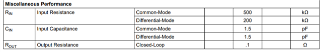
  4. What is the input resistance of the component?
  5. What is the input capacitance of the component?

Best Regards
Markus

  • Hi Markus,

    1. Yes that is fine.
    2. Yes, as long as the differential supply voltage [Vs(+) - Vs(-)] is less than 12V total, you're fine. In your case it is 9V.
    3. Yes, the device is unity gain stable.
    4&5: Might vary a bit for the QML package, but it should be close to this:

    Best,

    Sam

  • In addition Markus, 

    The LMH6628 is a dual, be careful what you do with the other channel

    5Vpp is a high swing for this 550V/usec slew rate device. Your 12MHz requires 190V/usec - so it is adequate but you should not expect very low harmonic distortion depending on your load - and what is that? 

    I was looking for a TINA model, here is one from the TINA V11 library - transistor level (no TINA file in product folder). 

    LMH6628 TINA model.TSC

  • Hello Michael, thanks for your fast response.

    The second channel will also get a signal of 0V to 5V / 12MHz. Actually the waveform of the signal is similar to a rectangular waveform: Every 83ns the signal changes by a maximum of 3.4V in the range of 0V to 5V.
    The output signal shall settle within 10ns => 340V / µs.

    What is the topic with harmonic distortion, does it depend of the slew rate?

    Load: The output of the buffer is connected to a differential ADC driver with a (calculated) input impedance of 1k8

    Best Regards, Markus.

  • Hi Markus,

    I believe Michael was referring to this performance behavior, where HD increases with output swing.

    You can also find the crosstalk as a function of frequency in the datasheet as well:

    Best regards,

    Sam