This thread has been locked.

If you have a related question, please click the "Ask a related question" button in the top right corner. The newly created question will be automatically linked to this question.

TL034: How to calculate the offset voltage

Part Number: TL034
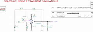
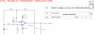
Other Parts Discussed in Thread: TINA-TI, LM318, OPA209

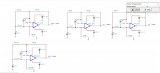
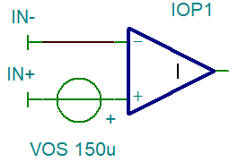
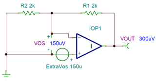
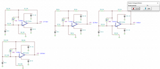
In the simulate circuit, Why does the offset voltage increase when the resistance value is changed?  the input common voltage do not change.

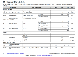
I guess it's due to Iib and Iio, but the Iib and Iio are too small, the max value is just 200pA,What is the cause of this?

  • This is an old OPAmp with a highly simplified Boyle macromodel from 1989. I don't think that this model of TL034 even models the input offset voltage. From your snippet of datasheet you can see that the typical input offset voltage of TL034 is 500µV. So the modelled input offset voltage shown in your simulation is entirely unrealistic anyway.

    What you see is just simulation artefacts, either coming from the oversimplified model or from the TINA-TI simulator itself.

    Kai

  • Hi Kai,

    thanks for your reply.

    your explain is right, i use the LM318 to resimulate, the offset voltage is 4mV and the specification is matched to Datasheet

    By the way, the external resistance of the op amp does not affect  the value of the bias voltage?

    in the simulation, the resistance is not the same, but the resistance ratio is the same, the ratio is 1.

  • Well, the LM318 is a different story because it contains bipolar transistors in the input stage sinking lots of input bias current. 150nA typical input bias current times 20k gives 3mV. So with the LM318 you will definitely see a change of output offset voltage when changing the resistor values in the feedback.

    Kai

  • Hello User,

    With the matching resistance, IIB won't matter. IIO does matter. IIO doesn't change the Vos (offset voltage) but it it does change the voltages in the resistors which affect the output voltage. 'IIO*R' is an input (referenced) voltage error, but the voltage isn't found at the input pins directly.

  • I think the offset voltage obtained by using the TINA simulation software is not correct.

    the below is a template example obtain from TI official website, the OP207 is a latest OP amplifier. 

    The simulation data are irregular, I want to get a match between the simulation data and the Datasheet, but now I find that they can not meet.

    for example, if the typical offset voltage is 35uV, I can test the offset voltage is 35uV in TINA when the input voltage is 0V. in this case, how to set the TINA?

  • The OP207??

  • User,

    I suggest increasing the Vos manually. 

    Kai, op amp in last question was OPA209 (not 207)

  • Same thing in a circuit