This thread has been locked.
If you have a related question, please click the "Ask a related question" button in the top right corner. The newly created question will be automatically linked to this question.
Original question:
XTR106: Design a 4-20mA transmitter for a 700 Ohm input impedance Load Cell
Replies: 21
Views: 993
Part Number: XTR106
Hi
I have to design a 4-20 mA transmitter circuit for a load cell with 520ohm impedance.
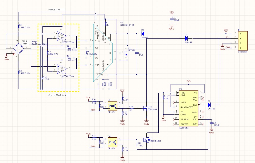
I used XTR106 and circuit that mentioned in figure 5 of XTR106 datasheet.
but i don't have any Vref voltag for supplying my sensor means the voltage is zero so my current is zero too. (Vreg is zero too)
my circuit is:
I don't know what is the problem. maybe the the XTR106 was damaged but all 5 ICs that i bought had a same result.
I would be thankful if someone could help me...
In reply to kai klaas69:
In reply to Amir Poursadegh:
Hi Amir, the whole XTR106 circuit is floating and the voltage at pin 6 is shifted by the voltage drop of output current across burden resistance (the load resistance which is connected from pin 3 to pin 2 of connector P1). So, you must not connect pin 7 or any other pin of XTR106 to GND! And it's not wise to use GND as a shield for the bridge either. Connect the shield to pin 6 instead. But take care that pin 6 is not connected to any foreign potential! Kai
Hi Kai thanks for your helpful answers... I will correct my circuit but my question is why I don't have Vref voltage? is it related to Vref and Vreg voltage?
Hi Kai It's not complete I have another part for cut the circuit and give constant current...but I test this circuit alone without another thing and results was same (i didn't use sheild pin as you mentioned)...are you sure if I connect GND to pin 7 of XTR106 (with a mosfet), the XTR106 would be damaged?
Hi Kai
this is the whole of my circuit
AD694 do it's duty well but XTR106 is not.