This thread has been locked.

If you have a related question, please click the "Ask a related question" button in the top right corner. The newly created question will be automatically linked to this question.

AMC1300: Parallel operation of the AMC1300 for current measurement.

Part Number: AMC1300

Dear sir,

we are trying to measure the current (4 ch) & voltage (4 ch) using AMC1300. All channels are connected in parallel. 

All the 8 qty of AMC1300 high side are supplied by 5V source PS1. All the 8 qty of AMC1300 low side are supplied by 5V source PS2. 

When we measure same current in all the four channel, everything works fine. we can able measure the same value in all the four channels. 

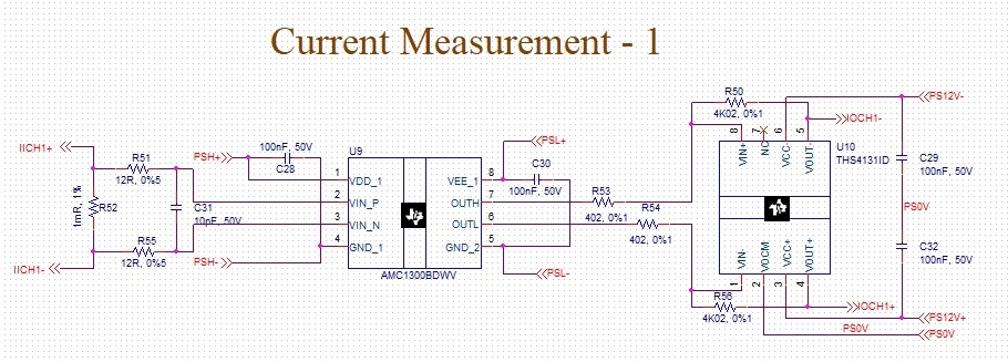
If we connect current measurement board to measure the three phase inverter output current, Resistance R51 and R55(as shown in the below picture) are burned.  All the filter resistance used in the current measurement circuits are burned. The voltage measurement circuit was working fine. 

please find the below attached project file.

voltage_current_signal_conditioning-2019-11-09T20-42.zip

Kindly guide us to proceed further in current measurement using AMC1300.

Thanking you.

Thanks & regards,

Rajasekaran.

  • Hi Rajasekaran,

    Can you send over a schematic in PDF format?  I can't open the file extensions that you sent for your AMC1300 project.  If you have four different voltage phases, I'm not seeing how you might have referred all VDD1 sources to the same 'PS1' power supply - in your schematic I see PSH+ and PSL+.  PSL+ for the 4 channels can most likely be the same source, but I believe you'll need separate PSH+ and PSH- for each channel.

  • Dear sir,

    please find the below schematic file. 

    Voltage and Current Measurement.pdf

    Could you please confirm the possibilities of sharing the power supply between high side of same voltage and current channels.? 

    Thanks & regards,

    Rajasekaran.

  • Hi Rajasekaran,

    Sorry for the delay, I was looking at you power supply parts and wanted to review your schematic.  I'm fine with your use of one power supply for the PSL+ and PSL- and the PS12V+/PS12V-, but you should tie all of the PSL- lines to the PS0V so that the low side has a common 'ground' or 0V reference.  Depending on the input source to J1/D1/D6, you might be able to use that voltage supply for VEE_1 and GND_2.

    For the high side supplies though, unless all four channels are looking at the same source, you can't tie them together.  You might be able to use the same supply for VICH1/IICH1, VICH2/IICH2, etc depending on how the load is being measured.  Do you have an overall block diagram showing how the voltage and currents are connected together?