Because of the holidays, TI E2E™ design support forum responses will be delayed from Dec. 25 through Jan. 2. Thank you for your patience.

This thread has been locked.

If you have a related question, please click the "Ask a related question" button in the top right corner. The newly created question will be automatically linked to this question.

MPY 634 AM Modulator

Other Parts Discussed in Thread: MPY634

Hi,

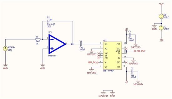
I want to use MPY634 for AM modulation. I used basic multiplier connection mentioned in MPY634 datasheet.

I have following issues:

1) When I connect carrier signal on X1 I become on X1 an input voltage offset of cca -0.2V. The input carrier signal measured behind C2 (see my connection) has no offset.

2) The AM output is very distorted and not behave like AM. When I change the input amplitude of carrier or MP3_in signal, there is only change in the amplitude of modulated signal. There is no change in modulation index. I need the standard AM like shown here:

http://en.wikipedia.org/wiki/File:Amplitude_Modulated_Wave-hm-64.svg

Please can you explain me what is wrong here?

Thank you.

Petr Duga

Here is my MPY634 connection:

Here are MPY634 signals:

where:

CH1: pin 1 (X1)- 900kHz, 1.04Vpp, -253mV DC, carrier

CH2: pin 6 (Y1)- 1kHz,  1.06Vpp, -16mV DC, MP3_IN

CH3: pin 12 (Out) - modulated signal

  • Hello Petr,

    MPY634 data sheet Figure 9 shows the correct connection for the linear, AM modulator function. Y1 and Z2 must be connected togther and that connection is where the carrier is applied; not at the X1 input. The low frequency modulating signal is applied to the X1 input.

    Also, the X1 and Y1+Z2 inputs connections must have a dc return to ground. Otherwise, they have no dc input bias current return. Simply add a resistance from these inputs to ground. The MPY634 input current is typically 800 nA, so you don't want to make the resistance to large if you want to avoid adding a dc offset. I would try 10 kilohms, or something less.

    Regards, Thomas

    PA - Linear Applications Engineering

  • Thank you Thomas,

    I reconfigure my connection by your pieces of advice. And AM works good. I use potentiometer to change SF too. I made good expirience with replacement of C3 in my scheme with 10K resistor.


    Now I would like to do the amplitude demodulation with direct-conversion.

    My idea is to use MPY in configuration Fig. 9 and LP filter.

    Do you think is this the best way? (I mean use Fig. 9)

    Best regards

    Petr Duga

  • Hello Petr,

    I do not think the MPY634 figure 9 circuit can be used for direct AM demodulation. AM can be demodulated using the multiplier as a product detector, but a signal having the same frequency as the modulated signal's carrier must be injected into one of the Z inputs. The resulting demodulated AM will have an audio beat note if the injected frequency and the carrier are not matched precisely. It is probably overly complicated for simple AM demodulation.

    There is a another method of detecting an AM signal using a multiplier, but also requires a zero-crossing detector (comparator) and an output low-pass filter. It seems overly involved too.

    I would do a Google Image search on AM demodulation and many simple circuits will be displayed. Some provide an easy, low cost solution.

    Regards, Thomas

    PA - Linear Applications Engineering