This thread has been locked.

If you have a related question, please click the "Ask a related question" button in the top right corner. The newly created question will be automatically linked to this question.

TLV320AIC3204EVM-K: TLV320AIC3204EVM-K: The USB-ModemEVM interface not getting detected in Windows 10

Part Number: TLV320AIC3204EVM-K
Other Parts Discussed in Thread: TLV320AIC3204

Dear Team,

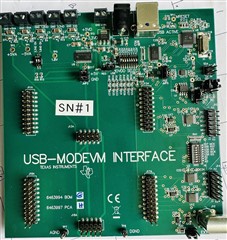
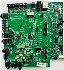
I wanted to bring to your attention that we have recently purchased the TLV320AIC3204EVM-K for our Audio development purposes. To proceed with the setup, I have downloaded the GUI tool from this source.

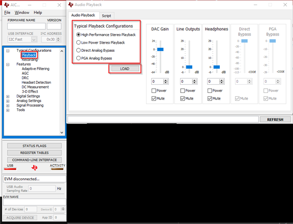
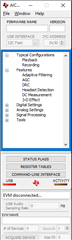
Afterward, I installed the AIC3204 CS tool and connected the TLV320AIC3204EVM-K board to my computer using the provided USB cable. It is worth mentioning that I have kept the board settings at their default values without making any modifications. run the tool as an administrator, I am unable to detect the device ready.

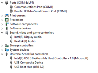
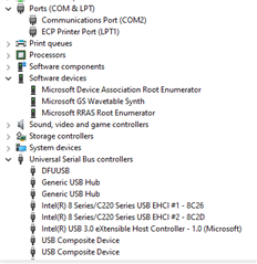
For your reference, I have attached a screenshot of the encountered error. Additionally, I have included a screenshot of the device manager it's not shown in the sound device list.

I would greatly appreciate your guidance on resolving this issue. My intention is to connect the EVM board to Windows using the USB cable and enable sound playback.

Thank you for your assistance.

Best regards,

Parashuram

  • Hi Parashuram,

    Thanks for bringing this up. This sounds similar to something we've seen before, but we're still investigating. You'll get an answer from our team by the end of the day.

    Thank you,
    Jeff McPherson

  • Hi Parashuram,

    As Jeff said, we have seen this happen before. Unfortunately, these can be pretty tricky solve.

    Based on the device manager screenshot, the USB-MODEVM is probably enumerating as DFUUSB. To confirm this, please disconnect the EVM and see if the driver goes away.

    Also, could you please share a picture of the board (both the MOD-Interface and the EVM itself)? I am sure the board is in the "as shipped condition" as you have stated, there are jumpers used in manufacturing that I would like to make sure are in the correct position. 

    Best,
    Andrew

  • Hello Andrew,

    Thanks  for your reply,

    Once the EVM kit is disconnected, the DFUUSB disappears. Please refer to the screenshot provided, which shows the EVM disconnected.

    Please find the attached Pictures of the EVM board.

    If there is a driver available for USB-MODEVM, I couldn't find it separately. If you have the driver, please provide a link to download it.

    Regards,

    Parashuram

  • Hello Team,

    I'm pleased to inform you that I have resolved the issue by flashing the EEPROM.

    Currently, I am in the process of connecting the TLV320AIC3204 daughter card to the Nvidia Jetson Linux-based AGX Orin development kit.

    To establish the connection, I disconnected the daughter card from the motherboard (USB-MODEVM) and supplied power from an external source through the P23 header, following the schematic. The codec is now operational, and I have been able to detect the correct I2C address. I have also checked the voltage levels on the daughter card, and they are within the range.

    I have connected the I2S and I2C signals from the Nvidia AGX Orin dev kit to the TLV320AIC3204 daughter card. After enabling the device driver for the codec, I can confirm that the I2C address is being detected (UU) on the Orin Dev kit.

    I see that the Orin Dev kit is properly sending signals to the codec. The MCLK is measured at 11.07MHz, BCLK at 2.80MHz, and WCLK at 44.1kHz, indicating that the signals from the Orin side are being transmitted correctly. For your reference, I have attached a screenshot capturing these details.

    I didn't get why I'm not able to hear the output sound from the codec board.

    I have noticed that in Windows, after connecting the TLV320AIC3204EVM kit via USB, I need to click the playback button in the AIC3204 CS software tool then only I can able hear the sound.

    Are there any specific mixer settings or scripts that need to be executed on the Orin Dev kit in order to hear sound output from the codec?

    Your assistance would be greatly appreciated. 

    Regards,

    Parashuram

  • Hi Parashuram, 

    I am glad to hear that you found a way around the issue. From my understanding, you bypassed the USB-MOD interface and are using the EVM as a standalone solution. Is this correct? If you still want to use the MOD-Interface, you can try the process in How-to-Revive-a-USB-Audio-EVM.pdf. Note that if you use this process w13 may need to be removed for the process. 

    However, it sounds like using an external I2C is working for you. By default the CODEC will be muted on power up. You can use the below scripts provided in the GUI to see typical CODEC start sequences. You can find the test script in text format in the "script" tab. The GUI also features a "command line interface" that can record the I2C writes made while using the GUI. 

    I hope this helps.

    Best,
    Andrew

  • Hello Andrew,

    From my understanding, you bypassed the USB-MOD interface and are using the EVM as a standalone solution. Is this correct?

    Exactly correct.

    Can you please provide guidance on how to unmute the CODEC?

    The AIC3204CS GUI tool is compatible with Linux and can be installed on the Linux operating system.

    Will the script work on Linux?

    Regards,

    Parashuram 

  • Hello Parashuram, 

    The GUI is not compatible with Linux unfortunately. However, the script that is used in the GUI can be used as a reference and repurposed for your system. The TLV320AIC3204 Application Reference Guide also contains examples scripts in section 4 that might be helpful as well (see 4.0.1 Stereo DAC Playback with 48ksps Sample Rate and High Performance). Also, Section 3 has additional information on device initialization. 

    The Output control register also begin around table 5.3.14 Page 1 / Register 16: HPL Driver Gain Setting Register - 0x01 / 0x10 (P1_R16) of the reference guide. I2C addresses will unmute and route these registers as needed. 

    Best, 
    Andrew

  • Hello Andrew,

    Thank you for your response. I have made attempts using the methods described below.

    Method 1: 

    You can use the below scripts provided in the GUI to see typical CODEC start sequences.

    I connected the EVM board in a standalone method by turning off switches SW2.4, SW2.5, and SW2.6. So, I connected the I2S signals to the corresponding pins on the P22 header and the I2C signals to the respective pins on the P12 header.

    After connecting, I played some audio and loaded the playback settings through the graphical user interface. However, instead of hearing the expected audio, I only heard a noise only. I double-checked the I2S signals while the audio was playing, and they appeared to be functioning properly.

    Method 2: 

    I have gone through TLV320AIC3204 Application Reference Guide and attempted to configure the device using I2C, but unfortunately, the settings were not applied correctly.

    I'm uncertain if I am using the correct command to configure the output control registers. Currently, I am using the following command: "sudo i2cset -f -y 7 0x18 -w 30 00 00," but it is producing an error.

    Could you please guide me on the correct procedure for applying the output control register using the I2C address?

    Regards,

    Parashuram 

  • Hello Parashuram,

    The set up in Method 1 sounds correct, I believe the issue is with the register writes outlined in Method 2/ 

    The TLV320AIC3204 responds to a 7-bit I2C address of 0x18 (see 9.3.8.1 I 2C Control), while the EVM user guide uses the TAS1020 to convert USB signals to I2C, the TAS1020 has an address of 0x30.  Since you are using external I2C this will bypass the TAS1020 and interface directly with the AIC3204 using the 0x18 address. 

    This means that in order to write a value 0x00 to register 0x00, the command would need to be -w 18 00 00 (assuming this is the correct usage of the Linux command). What is the Linux error? I assume the error is something like "error: write failed" or "I2C address not found".

    Also note, when looking up this command I found some warnings about using the -f sub command. I do not suspect this to specifically cause issuse with TI's device, however I wanted to bring this up. 

    Also, if you are using the I2S please ensure that J14 and J15 are configured as well (user's guide 2.4 Digital Signal Connection)

    Best,
    Andrew

  • Hello Andrew,

    I tried to write a register for codec address 0x18 using the command "i2cset -f -y 0x18 0x00 0x30". In this command, 0x00 represents the register and 0x30 represents the value. By executing this command, I am able to successfully write to the register. However, if I don't include the "-f" flag, an error occurs stating that the resource is busy, and I am unable to write to the register.

    The default value(after reboot) for the I2C address 0x18 is not functioning as expected. I have attached a screenshot for reference.

    I see in Application Reference Guide that in order to unmute, a value of 40 needs to be set in a specific register. However, I'm unsure which register exactly should be written to.

    Could you please provide guidance on the necessary settings for the I2C in order to play audio through the headphone?

    Here are the DTS and mixer settings I am currently using. This mixer configuration should theoretically work, but it is not functioning as intended.

    Please let me know if I have missed anything in these settings.


    Fullscreen
    1
    2
    3
    4
    5
    6
    7
    8
    9
    10
    11
    12
    13
    14
    15
    16
    17
    18
    19
    20
    21
    /*Added Audio codec DT Changes*/
    i2c@c250000 {
    aic32x4: tlv320aic32x4@18{
    compatible = "ti,tlv320aic32x4";
    reg = <0x18>;
    //clocks = <&bpmp TEGRA234_CLK_AUD_MCLK>;
    clocks = <&bpmp_clks TEGRA234_CLK_AUD_MCLK>;
    clock-names = "mclk";
    status = "okay";
    dv-supply = <&battery_reg>;
    av-supply = <&battery_reg>;
    iov-supply = <&battery_reg>;
    #sound-dai-cells = <1>;
    sound-name-prefix = "tlv";
    };
    };
    ...
    tegra_sound: sound {
    compatible = "nvidia,tegra186-ape";
    nvidia-audio-card,name = "NVIDIA Jetson AGX Orin APE";
    XXXXXXXXXXXXXXXXXXXXXXXXXXXXXXXXXXXXXXXXXXXXXXXXXX


    Fullscreen
    1
    2
    3
    4
    5
    6
    7
    8
    9
    10
    11
    12
    13
    14
    15
    16
    17
    18
    19
    20
    21
    amixer -c APE cset 'ADMAIF1 Mux' 'I2S1'
    amixer -c APE cset 'I2S1 Mux' 'ADMAIF1'
    amixer -c APE cset name='tlv Auto-mute Switch' 0
    amixer -c APE cset name='tlv HP DAC Playback Switch' 1
    amixer -c APE cset name='tlv HP Driver Gain Volume' 0
    amixer -c APE cset name='tlv HPL Output Mixer IN1_L Switch' 1
    amixer -c APE cset name='tlv HPR Output Mixer IN1_R Switch' 1
    amixer -c APE cset name='tlv HPL Output Mixer L_DAC Switch' 1
    amixer -c APE cset name='tlv HPR Output Mixer R_DAC Switch' 1
    amixer -c APE cset name='tlv LO DAC Playback Switch' 1
    amixer -c APE cset name='tlv LO Driver Gain Volume' 0
    amixer -c APE cset name='tlv LOL Output Mixer L_DAC Switch' 1
    amixer -c APE cset name='tlv LOR Output Mixer R_DAC Switch' 1
    amixer -c APE cset name='tlv PCM Playback Volume' 130
    XXXXXXXXXXXXXXXXXXXXXXXXXXXXXXXXXXXXXXXXXXXXXXXXXX

    Regards,

    Parashuram

  • Hello Parashuram,

    I am unsure how the two scripts work, however when you say:

    The default value(after reboot) for the I2C address 0x18 is not functioning as expected. I have attached a screenshot for reference.

    Does the reboot cycle power to the CODEC? This will return the CODEC to the default register configurations. 

    Also, is the CODEC a master or slave in this configuration? Overall, more information will be needed here. What output of the EVM are you trying to use? Reference Guide sample script "4.0.1 Stereo DAC Playback with 48ksps Sample Rate and High Performance" can be used to output using the Headphone output.


    Fullscreen
    1
    2
    3
    4
    5
    6
    7
    8
    9
    10
    11
    12
    13
    14
    15
    16
    17
    18
    19
    20
    21
    Assumption
    AVdd = 1.8V, DVdd = 1.8V
    MCLK = 12.288MHz
    Ext C = 47uF
    Based on C the wait time will change.
    Wait time = N*Rpop*C + 4* Offset ramp time
    Default settings used.
    PLL Disabled
    DOSR 128
    # Initialize to Page 0
    w 30 00 00
    # Initialize the device through software reset
    w 30 01 01
    # Power up the NDAC divider with value 1
    w 30 0b 81
    # Power up the MDAC divider with value 2
    w 30 0c 82
    # Program the OSR of DAC to 128
    w 30 0d 00
    w 30 0e 80
    # Set the word length of Audio Interface to 20bits PTM_P4
    XXXXXXXXXXXXXXXXXXXXXXXXXXXXXXXXXXXXXXXXXXXXXXXXXX

    Lines 41 to 62 is where the DAC is routed, and headphone outputs are enabled.

    Best,
    Andrew

  • Hello Andrew,

    Does the reboot cycle power to the CODEC? This will return the CODEC to the default register configurations. 

    No, it will remain in the same configuration after restarting.

    is the CODEC a master or slave in this configuration?

    The audio codec is a slave device. 

    What output of the EVM are you trying to use?

    I've plugged in my headphones to the headphone output jack. I'm anticipating that sound will come through the the headphone output jack, and later I can test the line out and microphone.

    I referred to the playback script from the script tab in the GUI and configured the I2C settings accordingly. Some registers were able to be set, and some register not able set. I have attached a screenshot for your reference.

    The clock settings in the AGX Orin match the ones you mentioned in the script tab's clock settings:

    Fullscreen
    1
    2
    3
    4
    5
    6
    ###############################################
    # Clock Settings
    # ---------------------------------------------
    # The codec receives: MCLK = 11.2896 MHz,
    # BLCK = 2.8224 MHz, WCLK = 44.1 kHz
    ###############################################
    XXXXXXXXXXXXXXXXXXXXXXXXXXXXXXXXXXXXXXXXXXXXXXXXXX

    But still why I'm not able to hear sound coming from the headphone output jack? Please find the attached capture of the I2S signals from AGX Orin.

    Regards,

    Parashuram

  • Hi Parashuram,

    I referred to the playback script from the script tab in the GUI and configured the I2C settings accordingly. Some registers were able to be set, and some register not able set. I have attached a screenshot for your reference.

    What registers are not able to be set?

    But still why I'm not able to hear sound coming from the headphone output jack? Please find the attached capture of the I2S signals from AGX Orin.

    I cannot tell what the signals are in this scope shot. What are you using as input to the CODEC? Is the green line DIN from the AGX Orin?

    Best,
    Andrew 

  • Hello Andrew,

    What registers are not able to be set?

    I have executed the command "i2cset -f -y 7 0x18 0x01 0x01" to configure a particular register. However, I have noticed that the change is not being reflected in the associated register. I have attached a screenshot for your reference.

    Could you please guide me on how to set the registers mentioned below?

    Fullscreen
    1
    2
    3
    4
    5
    6
    7
    8
    9
    10
    11
    12
    13
    14
    15
    16
    17
    # Route LDAC/RDAC to HPL/HPR
    w 30 0c 08 08
    #
    # Route LDAC/RDAC to LOL/LOR
    w 30 0e 08 08
    #
    # Power up HPL/HPR and LOL/LOR drivers
    w 30 09 3C
    #
    # Unmute HPL/HPR driver, 0dB Gain
    w 30 10 00 00
    #
    # Unmute LOL/LOR driver, 0dB Gain
    w 30 12 00 00
    # DAC => 0dB
    w 30 41 00 00
    XXXXXXXXXXXXXXXXXXXXXXXXXXXXXXXXXXXXXXXXXXXXXXXXXX

    I cannot tell what the signals are in this scope shot.

    What are you using as input to the CODEC?

    The input to the codec is AGX Orin I2S signals, and I have attached a connection diagram and signal names.

    Regards,

    Parashuram 

  • Hi Parashuram,

    I have executed the command "i2cset -f -y 7 0x18 0x01 0x01" to configure a particular register. However, I have noticed that the change is not being reflected in the associated register. I have attached a screenshot for your reference.

    Register 0x01 is the software reset register. Writing a value of 0x01 to this register resets the device. This but is self-clearing (see below) and will return to default. This bit is cleared so the device is not held in the reset state. For this reason, the value will return to 0x00 after the device is reset. 

    Could you please guide me on how to set the registers mentioned below?

    I do not know the specifics of your application. The configuration for the registers above are correct. (e.g. Unmuted and powered on). Please configure those registers according to the register map tables in section 5 of the TLV320AIC3204 Application Reference Guide if more information is needed. I have attached one of the GUI scripts below again for reference.

    Fullscreen
    1
    2
    3
    4
    5
    6
    7
    8
    9
    10
    11
    12
    13
    14
    15
    16
    17
    18
    19
    20
    21
    ###############################################
    # High Performance Stereo Playback
    # ---------------------------------------------
    # PowerTune mode PTM_P3 is used for high
    # performance 16-bit audio. For PTM_P4,
    # an external audio interface that provides
    # 20-bit audio is required.
    #
    # For normal USB Audio, no hardware change
    # is required.
    #
    # If using an external interface, SW2.4 and
    # SW2.5 of the USB-ModEVM must be set to
    # HI and clocks can be connected to J14 of
    # the USB-ModEVM.
    #
    # Audio is routed to both headphone and
    # line outputs.
    ###############################################
    XXXXXXXXXXXXXXXXXXXXXXXXXXXXXXXXXXXXXXXXXXXXXXXXXX

    Thank you for labeling the scope shot. I think this is most likely your issue. The Host controller appears to be providing the CODEC with a WCLK that is not an I2S formatted WCLK. Section 2.6 Audio Digital I/O Interface of the TLV320AIC3204 Application Reference Guide shows the possible configuration modes of the ASI interface. By default, the CODEC will use the configuration shown in 2.6.3 I2S Mode. 

    The Scope shot seems to show that the host controller is providing the CCODEC some other format. Possibly 2.6.4 DSP Mode.  

    Please either the host and CODEC to use the same ASI format. 

    Best,
    Andrew