


Hi, support team
My customer has the questions as follow:
I am using CDCEL913.
I can output integer frequency, such as 33MHz
However, once there are decimals, such as 32.768 MHz, the output is incorrect.
For example, I set 32.768MHz, but my oscilloscope measures 4MHz.
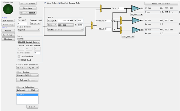
This is my register configuration, which is obtained through Pro-Clock software:
Bit  ==>  76543210
Byte 00 - 00000001
Byte 01 - 00000000
Byte 02 - 10110100
Byte 03 - 00000111
Byte 04 - 00000010
Byte 05 - 01010000
Byte 06 - 01000000
Byte 07 - 00000000
Byte 08 - 00000000
Byte 09 - 00000000
Byte 10 - 00000000
Byte 11 - 00000000
Byte 12 - 00000000
Byte 13 - 00000000
Byte 14 - 00000000
Byte 15 - 00000000
Byte 16 - 00000000
Byte 17 - 00000000
Byte 18 - 00000000
Byte 19 - 00000000
Byte 20 - 00001101
Byte 21 - 00000010
Byte 22 - 00000000
Byte 23 - 00000000
Byte 24 - 11100000
Byte 25 - 00000010
Byte 26 - 10100011
Byte 27 - 10000011
Byte 28 - 11100000
Byte 29 - 00000010
Byte 30 - 10100011
Byte 31 - 10000000
And this is my C configuration code. I can make sure that the register is written in, because the output integer frequency is OK.
#include "cdce913.h"
#include "iic.h"
#include <stdbool.h>
#include "math.h"

/************************************************
* File Name: @@@.c

* Author:xykj

* Date:2019.11.29

* function:cdce913

*************************************************/


void CDCE913_Init_invar(void)
{
  cdce913_I2C_WriteByte(0x02, 0x34);    //
  cdce913_I2C_WriteByte(0x03, 0x1A);    //y1·ÖƵ
  cdce913_I2C_WriteByte(0x04, 0x02);    //s0=0,s0=1¾ùѡͨ
  cdce913_I2C_WriteByte(0x05, 0x50);    //10PF ¾§ÕñµçÈÝ
  cdce913_I2C_WriteByte(0x06, 0x40);


  cdce913_I2C_WriteByte(0x12, 0X00);    //SSC1_1[5:3] AND  SSC1_0[2:0]  XXX XXX
  cdce913_I2C_WriteByte(0x13, 0X00);    //s0=0,Ñ¡Ôñfvco1   s0=1,Ñ¡ÔñFVCO_0
  cdce913_I2C_WriteByte(0x14, 0x6D);    //ʹÓÃPLL1£¬Y2ʹÓÃpdiv2£¬y3ʹÓÃpdiv3 0110 1101 (6D)
  cdce913_I2C_WriteByte(0x15, 0X02);    //S0=0,S0=1´ò¿ª

  cdce913_I2C_WriteByte(0x16, 0X7D);    //y2·ÖƵ 0Ϊ¹Ø
  cdce913_I2C_WriteByte(0x17, 0X00);    //y3·ÖƵ 0Ϊ¹Ø


  cdce913_I2C_WriteByte(0x18, 0X7C);    //N
  cdce913_I2C_WriteByte(0x19, 0XE2);    //N
  cdce913_I2C_WriteByte(0x1A, 0XC2);    //R
  cdce913_I2C_WriteByte(0x1B, 0X68);    //Q


  cdce913_I2C_WriteByte(0x1C, 0X7C);    //N
  cdce913_I2C_WriteByte(0x1D, 0XE2);    //N
  cdce913_I2C_WriteByte(0x1E, 0XC2);    //R
  cdce913_I2C_WriteByte(0x1F, 0X68);    //Q


}

//void CDCE913_Init_invar(void)
//{
//  cdce913_I2C_WriteByte(0x02, 0xB4);    //
//  cdce913_I2C_WriteByte(0x03, 0x7E);    //y1·ÖƵ
//  cdce913_I2C_WriteByte(0x04, 0x02);    //s0=0,s0=1¾ùѡͨ
//  cdce913_I2C_WriteByte(0x05, 0x50);    //10PF ¾§ÕñµçÈÝ
//  cdce913_I2C_WriteByte(0x06, 0x40);
//

//  cdce913_I2C_WriteByte(0x12, 0X00);    //SSC1_1[5:3] AND  SSC1_0[2:0]  XXX XXX
//  cdce913_I2C_WriteByte(0x13, 0X00);    //s0=0,Ñ¡Ôñfvco1   s0=1,Ñ¡ÔñFVCO_0
//  cdce913_I2C_WriteByte(0x14, 0x2D);    //ʹÓÃPLL1£¬Y2ʹÓÃpdiv2£¬y3ʹÓÃpdiv3 0110 1101 (6D)
//  cdce913_I2C_WriteByte(0x15, 0X02);    //S0=0,S0=1´ò¿ª
//
//  cdce913_I2C_WriteByte(0x16, 0X00);    //y2·ÖƵ 0Ϊ¹Ø
//  cdce913_I2C_WriteByte(0x17, 0X00);    //y3·ÖƵ 0Ϊ¹Ø


//  cdce913_I2C_WriteByte(0x18, 0X6A);    //N
//  cdce913_I2C_WriteByte(0x19, 0X59);    //N
//  cdce913_I2C_WriteByte(0x1A, 0X82);    //R
//  cdce913_I2C_WriteByte(0x1B, 0X89);    //Q


//  cdce913_I2C_WriteByte(0x1C, 0X6A);    //N
//  cdce913_I2C_WriteByte(0x1D, 0X59);    //N
//  cdce913_I2C_WriteByte(0x1E, 0X82);    //R
//  cdce913_I2C_WriteByte(0x1F, 0X88);    //Q
//
//
//}

#define CLK_IN    26

void CDCE_Init_set(float f_out)
{
  uint8_t read_back;
  uint8_t i = 0;
  uint32_t M, N,  Q, R;
  float Pdiv;
  uint8_t reg18, reg19, reg1A, reg1B;
  int32_t P;
  float f_vco = f_out;
  bool result    = false;
  uint8_t f_range;


  while (f_vco < 80)
  {
    i++;
    f_vco = f_out * i;
  }


  while (f_vco < 231)
  {
    for (N = 4095; N > 0; N--)
    {
      for (M = 511; M > 0; M--)
      {
        if ((N * CLK_IN / M) == f_vco)
        {
          {
            result = true;
            break;
          }
        }
      }
      if (result)
      {
        break;
      }
    }
    if (result)
    {
      break;
    }
    else
    {
      i++;
      f_vco = f_out * i;
    }
  }


  P = 4 - (int)((log((double)N / (double)M))/log(2));
  if (P < 0)
  {
    P = 0;
  }
  Q = (int)((double)N * pow(2, (double)P) / (double)M);
  R = (double)N * pow(2, (double)P) - M * Q;


  if (f_vco < 125)
  {
    f_range = 0;
  }
  else if ((f_vco >= 125) && (f_vco < 150))
  {
    f_range = 1;
  }
  else if ((f_vco >= 150) && (f_vco < 175))
  {
    f_range = 2;
  }
  else
  {
    f_range = 3;
  }


  Pdiv = f_vco/ f_out;


  cdce913_I2C_WriteByte(0x02, 0xB4);
  cdce913_I2C_WriteByte(0x03, (uint8_t)Pdiv);
  cdce913_I2C_WriteByte(0x04, 0x02);
  cdce913_I2C_WriteByte(0x05, 0x50);
  cdce913_I2C_WriteByte(0x06, 0x40);

  cdce913_I2C_WriteByte(0x12, 0x00);
  cdce913_I2C_WriteByte(0x13, 0x00);
  cdce913_I2C_WriteByte(0x14, 0x6D);        //Y2,Y3¿ª¹Ø¿ØÖÆ£¬y1²»ÊǸÃÒý½Å¿ØÖÆ£¬¹Ì¶¨ÓÐY1
  cdce913_I2C_WriteByte(0x15, 0x02);

  cdce913_I2C_WriteByte(0x16, 0);
  cdce913_I2C_WriteByte(0x17, 0);


  reg18 = (N >> 4) & 0xFFF;
  reg19 = (N & 0xf) << 4 | (R & 0xf0) >> 5;
  reg1A = (R & 0x1f) << 3 | ((Q >> 3) & 0x7);
  reg1B = (Q & 0x7) << 5 | (P & 0x07) << 2 | (f_range & 0x03);


  cdce913_I2C_WriteByte(0x18, reg18);
  cdce913_I2C_WriteByte(0x19, reg19);
  cdce913_I2C_WriteByte(0x1A, reg1A);
  cdce913_I2C_WriteByte(0x1B, reg1B);


  cdce913_I2C_WriteByte(0x1C, N);
  cdce913_I2C_WriteByte(0x1D, ((N & 0xf) << 4) | (R & 0xf0));
  cdce913_I2C_WriteByte(0x1E, (R & 0x0f) | (Q & 0xf0));
  cdce913_I2C_WriteByte(0x1F, ((Q & 0x07) << 5) | ((P & 0x07) << 2) | (f_range & 0x03));


}

//void CDCE_Init_set(uint16_t f_out)
//{
//  uint8_t read_back;
//  uint8_t i = 0;
//  uint32_t M, N, Pdiv, Q, R;
//  uint8_t reg18, reg19, reg1A, reg1B;
//  int P;
//  uint16_t f_vco = f_out;
//  bool result    = false;
//  uint8_t f_range;


//  while (f_vco < 80)
//  {
//    i++;
//    f_vco = f_out * i;
//  }


//  while (f_vco < 231)
//  {
//    for (N = 4095; N > 0; N--)
//    {
//      for (M = 511; M > 0; M--)
//      {
//        if ((N * CLK_IN / M) == f_vco)
//        {
//          {
//            result = true;
//            break;
//          }
//        }
//      }
//      if (result)
//      {
//        break;
//      }
//    }
//    if (result)
//    {
//      break;
//    }
//    else
//    {
//      i++;
//      f_vco = f_out * i;
//    }
//  }


//  P = 4 - (int)((log((double)N / (double)M))/log(2));
//  if (P < 0)
//  {
//    P = 0;
//  }
//  Q = (int)((double)N * pow(2, (double)P) / (double)M);
//  R = (double)N * pow(2, (double)P) - M * Q;


//  if (f_vco < 125)
//  {
//    f_range = 0;
//  }
//  else if ((f_vco >= 125) && (f_vco < 150))
//  {
//    f_range = 1;
//  }
//  else if ((f_vco >= 150) && (f_vco < 175))
//  {
//    f_range = 2;
//  }
//  else
//  {
//    f_range = 3;
//  }


//  Pdiv = f_vco/ f_out;


//  cdce913_I2C_WriteByte(0x02, 0xB4);
//  cdce913_I2C_WriteByte(0x03, (uint8_t)Pdiv);
//  cdce913_I2C_WriteByte(0x04, 0x02);
//  cdce913_I2C_WriteByte(0x05, 0x50);
//  cdce913_I2C_WriteByte(0x06, 0x40);
//
//  cdce913_I2C_WriteByte(0x12, 0x00);
//  cdce913_I2C_WriteByte(0x13, 0x00);
//  cdce913_I2C_WriteByte(0x14, 0x6D);        //Y2,Y3Ñ¡Ôñ
//  cdce913_I2C_WriteByte(0x15, 0x02);
//
//  cdce913_I2C_WriteByte(0x16, 0);
//  cdce913_I2C_WriteByte(0x17, 0);


//  reg18 = (N >> 4) & 0xFFF;
//  reg19 = (N & 0xf) << 4 | (R & 0xf0) >> 5;
//  reg1A = (R & 0x1f) << 3 | ((Q >> 3) & 0x7);
//  reg1B = (Q & 0x7) << 5 | (P & 0x07) << 2 | (f_range & 0x03);


//  cdce913_I2C_WriteByte(0x18, reg18);
//  cdce913_I2C_WriteByte(0x19, reg19);
//  cdce913_I2C_WriteByte(0x1A, reg1A);
//  cdce913_I2C_WriteByte(0x1B, reg1B);


//  cdce913_I2C_WriteByte(0x1C, N);
//  cdce913_I2C_WriteByte(0x1D, ((N & 0xf) << 4) | (R & 0xf0));
//  cdce913_I2C_WriteByte(0x1E, (R & 0x0f) | (Q & 0xf0));
//  cdce913_I2C_WriteByte(0x1F, ((Q & 0x07) << 5) | ((P & 0x07) << 2) | (f_range & 0x03));


//}
Please help me see what the problem is.
Thanks so much.
Best regards,
Yuki
