This thread has been locked.

If you have a related question, please click the "Ask a related question" button in the top right corner. The newly created question will be automatically linked to this question.

question: 10MHz clock and interface recommendation

Other Parts Discussed in Thread: BUF602

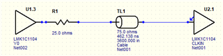
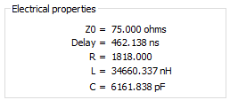
I want to send a 10 MHz clock signal for 300 ft from a modem to a Transceiver over 75 ohm coaxial cable.

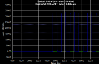
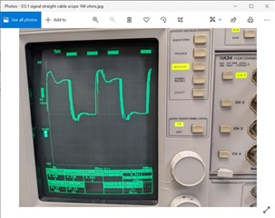
Can you recommend a low cost solution with drivers and receiver, with perhaps some pre-emphasis/conditioning to make sure the signal remains pure

Thanks,

Harry

  • Hello Harry,

    sorry for the late reply. I have run a quick simulation with a RG11/U coax cable. It seems that a 3.3V LVCMOS buffer could be a good option with another buffer at the receiver side to restore the signal.

    However, I reassign this to another product line to see if they have further inputs.

    Regards,

    Julian

  • Hello Harry,

    Please provide additional information about the 10MHz clock signal you need to send.  For example, is it an analog sine wave or a digitally generated square wave?  What are the voltage level requirements for the transmitted and received clocks?  What are the supply voltage requirements for the devices (3.3V, 5V, etc.)?

    At the moment it is not clear whether you need more of an analog or digital type solution.

    Regards,

    Jonathan

  • Hi Johnathan: The clock signa appears to be a digitally derived signal which does not appear to be too clean.  it may need some conditioning.  See attached image.

    The output voltage appears to be about 3.3 V,

    Thanks,  Harry

  • Hi Harry,

    Thanks for the confirmation on the type of clock signal you are trying to transmit.  It does look like it needs a bit of filtering and conditioning.  Some of this may be from reflections of the high frequency content of the signal used to create the "squared" edges and fast rise/fall times on your board and test equipment which is acting like an unterminated transmission line.

    Assuming we could get a cleaned up signal to transmit, you will also need to include some form of termination at the end of a 300 ft coax cable to prevent reflections. This will likely reduce the amplitude of the signal at the far end of the cable by up to 1/2 if a traditional 75 ohm termination resistor is used because it creates a voltage divider with the 75 ohm impedance of the cable.  A series resistor used as a "source" termination will not prevent reflections, but will try to attenuate them to a manageable level.  But this too will reduce the signal amplitude by a small amount.

    Do you have a required voltage level for the received signal, i.e. does it have to be 0-3.3V?

    Regards,

    Jonathan

  • Hi Harry,

    It appears you may only need a line driver buffer that is capable of driving the long transmission line 75-ohm coax cable. The LMK1C110x family of devices previously suggested could be used as a buffer but do not come in a single channel device.  It has a typical output impedance of 52.5 ohms and the impedance would need to be matched with a 25 ohm series resistor as shown.   A 75 termination resistor at the receiver side may also be needed to prevent reflections.  The output voltage levels are fixed and you would need to verify that the recovered voltage levels meet your requirements, or a small gain stage may be needed.

    A single-channel buffer such as the BUF602 could be used at both ends of the line and it has the ability to provide an external voltage reference to use as a mid-point reference for the recovered signal.

    Regards,

    Jonathan