- Ask a related questionWhat is a related question?A related question is a question created from another question. When the related question is created, it will be automatically linked to the original question.
This thread has been locked.
If you have a related question, please click the "Ask a related question" button in the top right corner. The newly created question will be automatically linked to this question.
Hi,
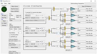
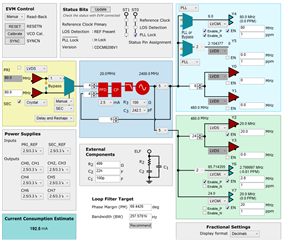
i am using LMK03328 right now to generate multi clocks for my system. i wish to generate one more 1.4MHz clock. But i failed to configurate it in TICS Pro. I saw the LMK03328 programming tutoiral. But i still cannot generate 1.4MHz clock. the minim clock i can do is 2.3MHz. The datasheet show the minim VCO output is 4800MHz, the maxim out devider is 8 and 256. so the minim output frequency is 4800/8/256=2.34375MHz. This is the minim freqeucy i can get withou error in the software. Why the datasheet show the minim output is 1MHz. How could i do it? Even i make the output from refence input dierectly, it still failed if make the input is 1.4MHz..
Thanks,
Shu
Hello Shu,
the divider depth of LMK03328 is not high enough to generate 1.4MHz from the PLLs. If ok, you can select the 80MHz PRIREF on one of OUT4 to OUT7 and divide by 57. That brings you close to 1.4MHz.
Otherwise you will need to change to LMK05318b which has a higher output divider depth. Alternatively CDCE6214.
regards,
Julian
Hi Julian,
Thank you very much. We thought to use LMK05318 and CDCI6214. But we won't use crystal in our application, or at least we can disable the crystal input for a moment. I believe LMK05318 must use a crystal to support basic frequency, and i don't find the crystal input disable option in the software. Do i misunderstand it?
About the CDCI6214. Our application jitter need lower than 750fs. i see the DCCI6214 maxim jitter can be 800fs in datasheet, so i reject it. i see the CDCE6214 jitter is worse to ps.
Could you please suggest me a device could generate clock low to 1.4MHz, at least four output, synchronization, LVCOM jitter is smaller than 750fs, could switch between two input clock, and crystal input is not necessary.
Thanks,
Shu
Hello Shu,
i can do that. But I need additional information because it sounds like we need to do jitter cleaning to some extend.
What is the integration range for the jitter requirements? Is it 12kHz to 20MHz?
Are the 750fs a requirement for the 1.4MHz signal?
How does the input signal look like? Do you have a phase noise plot? What is the input source?
What are the other frequencies that you need to generate?
regards,
Julian
Hi Julian,
the integration range 12kHz to 20MHz is good. it support 20MHz clock to a ADC with 100kHz analog bandwidth.
I need four output, two LVCOM 20MHz to ADC need 750fs jitter. 60-80MHz to my system controllor, 1.4MHz to another device. only 20MHz need low jitter.
Input are two 80MHz differential clocks from the system. if one loss, it could switch to another one.
Regards,
Shu
Hi Shu,
an alternative approach is to use a 20MHz xtal or XO feed this to CDCE937. This gives you good 500fs clocks.

regards,
Julian
Yes, i saw the picture. but our input frquency is fixed to a 80MHz source from another system device due to the system synchronization. and don't allow me to use oscillator/cyrstal for noise reduction. In the meantime, we can switch the input between two 80MHz source to aviod clock loss on any input. that is the reason i choice LMK03328 for most important low jitter 20MHz clock. then i found it doesn't work on the 1.4MHz. Other chips work on 1.4MHz but don't meet the jitter and input requirment.
Regards,
Shu
Hi Shu,
ok, in this case I can offer 2 solutions:
1. LMK05318b
2. CDCM6208 (generates 80/20/2.8MHz) + D-flipflop for a div by 2.

regards,
Julian
Hi Julian,
Yes, we thought LMK05318. But i wish to clear one thing with you. I have to use an oscillator/crystal at XO pin 31/32 on LMK05318/LMK05318B to provide the basic frequency and phase noise. Then the refernece inpt from DPLL provide synchronization. Am i right? So i cannot disable the XO input in the application, it will lose all output clocks, am i right?
If i can disable the XO input, LMK05318 is the beset choice for my design.
Regards,
Shu
Hi Shu,
your understanding is correct. Unfortunately the XO (or other reference) for the APLL's inside the LMK05318b needs to be available. Is there a problem of having a XO in your system?
regards,
Julian
Yes, our experience indicate the XO may impact some sensitive device in our system. so we normally use a clean source from the system directly. That is reason i choice LMK03328.
I may use a 80MHz oscillator at the secondary reference input when the board is debugging without the primary clock from system. i know the LMK03328 won't support 80MHz XO input, so i will use a LVCOM clock buffer between the LMK03328 and the oscillator. Will it work? That is another concern I wish to confirm with you.
Regards,
Shu
Hi Shu,
the frequency limitation resides in the inbuild oscillator stage that requires a passive crystal at the input.
If you use an active XO you can simply change the input stage to accept differential or LVCMOS signal. 80MHz is no problem in this case.
regards,
Julian
Hi Julian,
Wonderful! So i can save one clock buffer in my design.
I checked some similar devices such as LMK05318 and CDCI0614. May i think all these devices support the wide external input range if i use active crystal oscillator? the narrow crystal input range is only work for passive crystal oscillator. Make clear this will help me to use similar device in future project.
Regards,
Shu
Hi Julian,
Thank you very much. I will keep LMK03328 in my design, and then think other way to generate the 1.4MHz clock.
Regards,
Shu
Hi Shu,
that is nice to hear. I am closing that thread. Please post again, if you have further questions.
Regards,
Julian