This thread has been locked.

If you have a related question, please click the "Ask a related question" button in the top right corner. The newly created question will be automatically linked to this question.

Ultra-low noise, Low Voltage pulse (10 mV peak to peak, 10 nsec pulse duration)

Other Parts Discussed in Thread: TMUX1108, LMP7721, DAC80501, DAC1282, DAC11001A, OPA828, DAC7664, LMK5C33216, LMK5B33216, LMK04832, LMK04828, LMK04826, LMK04821, SN74LVC1G132, SN74LVC1G74, CDCE6214

Hi Texas,


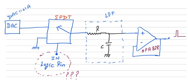
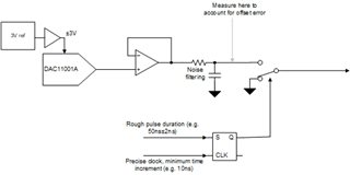
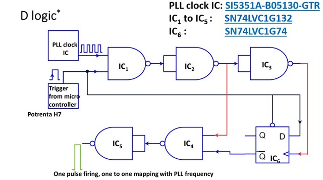
I want to generate an ultra-low noise, low voltage pulse (10 mV peak to peak, 10 nsec pulse duration) at a very high frequency. My requirement is to vary the pulse amplitude from 10 mV pp to 2.5 V pp, also pulse width variation from 10 nsec to 100 msec.

Could you please suggest possible efficient solutions which can be realized using discrete component ICs? This low-voltage, low-amplitude pulses will be given to the memory device array (in-house fabricated) via TMUX1108. Output current (1nA to 1mA) will be further sensed using LMP7721 multiple feedback gains.

Kindly help.

Thanks

Deepak

  • Hi Deepak,

    Could you please clarify your definition for very high frequency? Could you please quantify this?

    -Kang

  • Hi Kang,

    The frequency range for pulse generation will be from 10 MHz to 50 MHz maximum. Please let me know if you need more detailed clarification on any of the point in problem statement.

    Thanks

    Deepak

  • Hi Deepak,

    Our group (WI) within TI does not have such solution. I have forwarded your request to other teams to see if they have such solution. Thanks. 

    -Kang

  • Hi Deepak,

    We do not have any precision DACs that can switch at this speed, but you could consider using a precision DAC to create the amplitude voltage, and then use some analog switch or relay to generate the pulse width.  You did not really specify resolution, but consider a device like the DAC8050x family (DAC80501, for example).

    Thanks,

    Paul

  • Hi Paul,

    Thanks for reply. I wanted to understand following in detail:

    1. With DAC80501, in practice will we able to get resolution of micro-volts in amplitude of pulse? For ultra-low noise precision which architecture (say sigma-delta) will you suggest? Here, can we use 24 bit DAC1282 (although it does not fall in precision DAC category)?

    2. Are we suppose to operate precision DAC in constant amplitude (DC or < 1Hz mode)?

    3. Can we give PLL clock signal output (which gives apparantely good pulse frequency) to the enable/disable pin of analog mux/switch or there is more elegant way to achieve this in practice? 

    Kindly help us to design the most efficient topology.

    Thanks

    Deepak

  • 1. It depends on the range you select.  If you use 2.5V output range, then your VLSB size would be about 38µV/LSB.  If you want greater resolution, you could look at our 20-bit precision DAC11001A. 

    A delta-sigma type DAC like the DAC1282 can be used here as well, but you will want an extreme low-pass filter to remove high frequency noise and switching artifacts.  Noise will be the primary difficultly when using this DAC.

    2. I think a constant value (changed only to adjust the pulse amplitude) would be the easiest use case and would allow for aggressive low-pass filtering.

    3. I think you should instead use a SPDT switch to toggle between your peak amplitude Vhigh and your low value, Vlow (GND).  Each voltage, Vhigh and Vlow, would have a high bandwidth output amplifier driving the switch, something like the OPA828 or even higher bandwidth (at the cost of noise, offset error).

    Otherwise, I think you could consider your objectives for this circuit: why do you need such a precise amplitude and duration for the pulse? Are you trying to achieve a very precise energy?  Maybe some kind of precise current integrator that would accumulate charge could then discharge to create a pulse of a known energy value?

  • Hi paul,

    Thank you very much for the detailed clarifications. It made my day. The current integrator will not serve our purpose as we want to quantify a very high number of analogue states (>10k) from device measurement, using an integrator will ask us to compromise with precise information of analogue state.

    I have the follow-up queries:

    1. DAC11001A is a high output range voltage ie +/-10V (also need supply voltage > 5 Volt) however our requirement is to generate a maximum +/-2.5V (bipolar voltage pulse) down to 10 mV. We will not be utilizing the full capacity of this part as 2.5 V to 10 V will always be redundant for us, also achieving 10 mV from this wide output range DAC is another worrying factor. I could not find a single precision DAC (>=20 bit) which comes with a low output range (+/-5 V). Would you please suggest a low output range precision DAC say DAC7664 for more efficient outcomes?
    2. Please refer to the attached figure. What should be the most elegant way to control the logic pin of the SPDT switch? Is it through the GPIO port (which might not be very accurate) of a microcontroller or the output of the PLL clock IC or …? Kindly suggest this part in detail?
    3. Before feeding this low noise, amplitude pulse to the sensitive device, how can we address the noise and offset error which will be added by the driving amplifier (LPF + buffer)?

    Thanks

    Deepak

  • 1. The DAC11001A requires an external reference voltage, and can have a reference as low as 3V.  I recommend you configure the device to use a ±3V reference for a total of 6V output range.  You do need some 3V supply headroom, which means that you will have VCC = 6V and VSS = -6V.  That is needed for good operation near the endpoints, but if you are only using ±2.5V, then maybe VCC = 5V could be okay.  The minimum reference this can use is VREFP = 3V and VREFN=0V. 

    2. You could use a flip-flop as a re-clocking circuit.  For example, you have a precise clock from your PLL acting as a latch for the FF, then have a less accurate GPIO as your pulse signal.  The reclocking circuit would correct the GPIO pulse to the next PLL clock interval.

    3. You can measure the output before the SPDT and compensate for offset.

    Thanks,

    Paul

  • Hi Paul,

    Thanks for the detailed clarification.

    The mentioned solution in point 3 will generate multiple pulses in one go however we need to generate the precise pulse having precise control on pulse width from 50 nsec to 700 nsec.

    We are looking for circuit realization (similar to a programmable monostable multivibrator) where Width variation can be precisely controlled with digital programming. The latency between two adjacent pulses is not a worrying factor for us.  

    Kindly help.

    Thanks and Regards,

    Deepak

  • This is a bit tough for me, as I am not an expert in that field.  Let me see if someone from our clocking team can help.

  • Hi, we have some clock devices like LMK0482x (x=different VCO frequency option, LMK04828, LMK04826, and LMK04821 exist), LMK04832, LMK5C33216 and LMK5B33216 which support JEDEC JESD204B.

    The significance of JESD204B with respect to clocking is the definition of a SYSREF output.  SYSREF is commonly used to send 1 or more pulses to a device (typically ADC, DAC, or logic device) to synchronize their high frequency clocks internally.  (So each device gets a SYSREF clock and a device clock).

    So these clocking devices could be used to generate a single pulse.  The output amplitude would be much greater than 10 mV, however you could use resistor divider or some other method to reduce or translate output amplitude.

    So by using a 10 MHz SYSREF clock, you could produce single clock output pulse with 100 ns period, or 50 ns high pulse given 50% duty cycle.

    A ~0.714 MHz clock will give you a 700 ns pulse.

    Your ability to tune the pulse size is limited by frequency range of VCO and integer divider values.  However at suitably lower frequencies, the VCO range / "divide value of n" overlaps with VCO range / "divide value of n+1" for continuous frequency support.

    Does this sound like an option for you?

    73,
    Timothy

  • Hi Timothy,

    Thanks for your reply. I am worried about the complexity (feasibility too) of the JEDEC interface with the Arduino microcontroller as we are looking for a custom-made PCB for the same with minimum complexity. However, in a similar line, we developed a thought process (attached) to realize one pulse firing with TI logic gates and flops. Could you please evaluate it and give your suggestions to make this topology the best? Delay and timing constraints in practice (after assembling these parts on PCB) is another concern whether we will able to achieve ultra-fast, high resolution (minimum possible step increase in pulse width ie 50 nsec to 55 nsec) stable pulse.

    We thought to use the following components:

    1. SI5351A-B05130-GTR (PLL clock IC for generation of stable frequency from 2.5 kHz to 200 MHz)
    2. SN74LVC1G132 (high speed NAND gate)
    3. SN74LVC1G74 (high speed D Flip flop)


    Thanks

    Deepak

  • Hi Deepak,

    I apologize for the extreme delay.  Perhaps you have solved your issue.

    As for the circuit above, I don't think it works as intended.  I think you probably need some feedback into the D flipflop to ensure that only one pulse goes out.

    Also, I'm thinking the JESD204B option could be workable.  I can help you think through it if you want to go that option.  Of course having some discrete gates and FFs on the board may be more attractive that more complex programming.

    The only other comment I'd make is I'd use the clock device CDCE6214, can do outputs from 24 kHz to 328.125 MHz.

    73,
    Timothy

  • Here is some analysis for the JESD204B parts...

    And some results for some parts...

    73,
    Timothy

  • Hi Timothy

    Thank you very much. I think your suggestions will push my old design to outperform.

    I will work on it; if I face some issues, then I will revert to you.

    Thanks and Regards

    Deepak