- Ask a related questionWhat is a related question?A related question is a question created from another question. When the related question is created, it will be automatically linked to the original question.
This thread has been locked.
If you have a related question, please click the "Ask a related question" button in the top right corner. The newly created question will be automatically linked to this question.
Good Day,
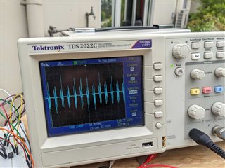
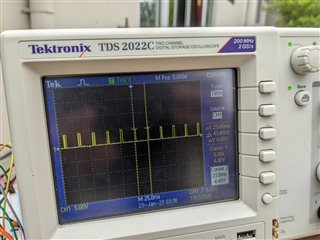
As part of a project I have implemented a circuit using a 555 timer to capacitively pick up spark plug impulses from a petrol engine. The purpose of this circuit is to convert a spark plug impulse and turn it into a square wave that can be read by a microcontroller. The circuit was initially implemented using a LM555 timer running at 3.3v. The below images show the input waveform (blue) from the engine spark plug, and the output from the 555 timer (yellow).


The layout of the circuit as as shown below:
Once proof of concept was achieved using the DIP package, I selected the TLC555 timer to replace the DIP package for a surface mount design. However, it appears that this IC does not produce the same results as the LM555 at 3.3v. The TLC555 either remains at 0v, or triggers intermittently until an operating voltage of 5v is reached. I would very much appreciate some assistance in either finding a part that has an equivalent performance to the LM555 or some tips for troubleshooting the problematic behaviour with the TLC555.
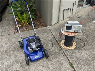
Below are some images of the initial testing, followed by an image of the non-functioning TLC555 circuit.

Thank you,
Regard,
Bjorn
Hello Bjorn,
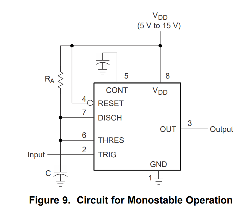
The issue most likely is due to the reset pin floating. It should be tied to the positive supply as shown below. If the pin is left floating you will get unpredictable behavior.

In addition a filter capacitor is recommended on the Cont pin in order to filter noise that can cause false triggering of the timer. There appears to be quite a bit of flux on the printed circuit board from soldering as well. Flux creates leakage paths and this can also cause undesirable behavior. Cleaning the flux off can also help.
Let me know if I can be of further assistance.
Best Regards,
Chris Featherstone
Thank you Chris,
After some testing, pulling up the reset pin fixed the issues. I have also added a pad for a capacitor in the next iteration of the board.
Best regards,
Bjorn