


Hi,
I am working on LMX2572 PLL on my new board and experiencing huge spurs near carrier frequency.
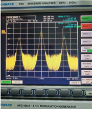
The spur is approx 3.15M Hz apart from carrier at 6GHz output. I am awared that the spur moves hundards kHz closer to carrier when switch output to 5GHz, and even hundards kHz closer at 4Ghz or 3.4Ghz output. The pll keeps locked during the whole process and output frequency is also correct.
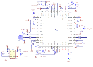
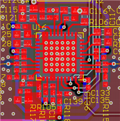
below is schematic / layout (PCB Material 4003C).
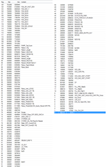
The input frequency is 100MHz, +3dBm from agilent N5182. Regs as below:
I have trid below items,
1, shut down all the other parts on board, just supply the PLL with 3.3V from Agilent E3632
2, program SPI over FPGA then MSP430 MCU
3, Replace the IC with a new one.
4, Re-solder loop filter components
but none of them helps.
The LMX2572 works fine on my old board, the old layout (as below) places all loop filter components near Pin35. My new layout divids the loop filter as datasheet suggested, could this be the root cause?

I verified the old board agian with exactlly the same OSC input/power supply/FPGA or MSP program; and it always worked fine.
I am quite confused where the huge spurs come from on my new board, did I miss anything on the new board or is there anything i can try?
Thanks in advance,
T.L.


