Other Parts Discussed in Thread: LMX2594,
Hi,
We are considering LMX2492 for one of our projects. We have the following questions:
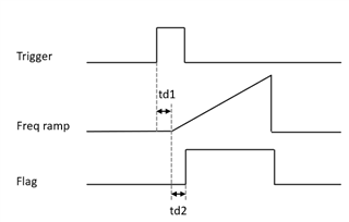
- Is there a time domain model to evaluate settling behavior?
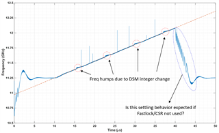
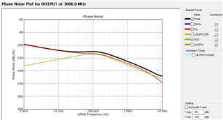
- If fast lock & cycle-slipping reduction is not used (consider max Icp already used in design), is there any internal techniques used to improve settling behavior (especially cycle slipping) compared to a classic frac-N PLL (look at the plot below)?
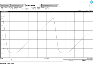
- We noticed that the in-band noise of LMX2492 (both flat and flicker) are a lot worse than some other TI PLLs (e.g., 9dB worse compared to LMX2594: -227 vs -236 & -120 vs -129)
- Is LMX2492 worse by design?
- What are the testing conditions under which the noise was characterized?
- The in-band noise of a PLL under FMCW modulation is elevated due to increased charge-pump activity compared to a static PLL in steady-state
- Is that considered in the flicker and flat noises reported in the datasheet?
- If yes, what FMCW conditions were assumed (chirp rate, etc)?
- If not, how much degradation should we expect when LMX2492 is under a certain modulation?
- Is that considered in the flicker and flat noises reported in the datasheet?
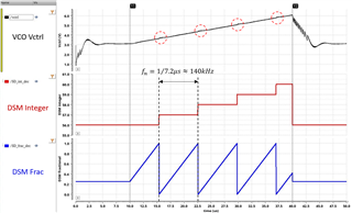
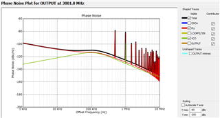
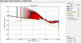
- For our project, we would need variation in both the integer as well as the fractional part of the feedback divider when PLL is under FMCW. For certain DSM implementations, we noticed that if the integer part varies, it causes freq humps in the frequency ramp profile which will lead to spurious radar output (look at the plot below).
- Are these humps expected in LMX2492?
- Any techniques used by design to mitigate this?