This thread has been locked.

If you have a related question, please click the "Ask a related question" button in the top right corner. The newly created question will be automatically linked to this question.

LMX2694-EP: There are many spurs in the output 4.3G signal

Part Number: LMX2694-EP
Other Parts Discussed in Thread: PLLATINUMSIM-SW

Hi Team,

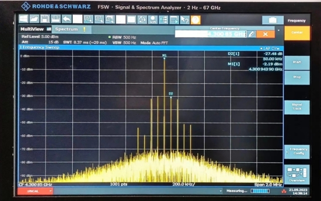
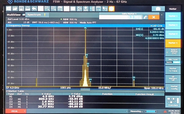
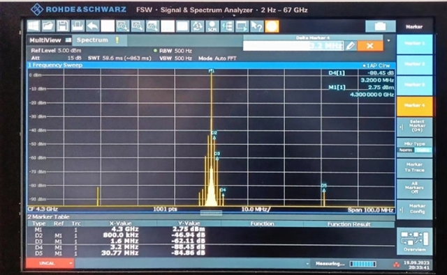
Using the LMX2694-EP chip to output signals, spurs were found on the near end of some of the band signals when testing the output of the 500-6000M band. For example, at 4300MHz, the spur is closest to the main signal. After checking the data, the customer found that it appeared to be the integer boundary spurs of the PLL, i.e. the phase frequency and its harmonics and output signal spurs, such as 112.88*35-4300=0.8M. Reducing the charge pump current improves spurs, but it would be better to keep them below 70dBc. According to the above calculations, the maximum spur should be around 122.88*n. 

The following figure shows the output 4300M signal spectrum: 

At 4300M, the configurations are as follows:

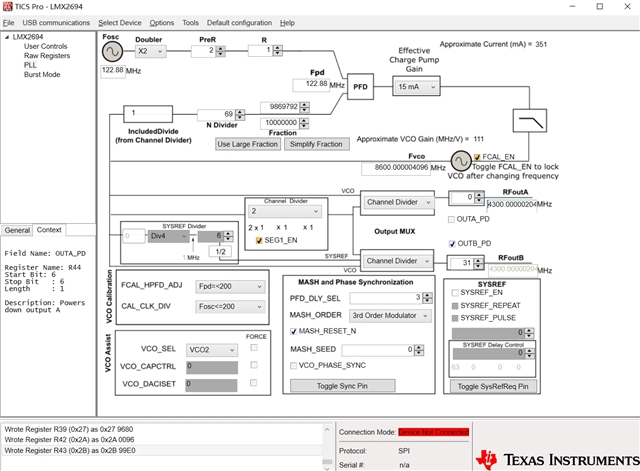
Could you help look into this case? Thanks.

Thanks and regards,

Cherry

  • Cherry,

    Spurs can be caused by mixing of the input (Fosc) and the VCO and output (Fvco and Fout).  In this case, the spurs are likely outside the loop bandwidth, so by reducing the charge pump current, you are reducing the loop bandwidth.  However, it could be better optimized if you re-designed the loop filter.

    If you re-design for a lower loop bandwidth, this would help, but actually using a higher order (3rd or 4th) order loop filter would likely help as well as these spurs are far outside the loop bandwidth.  Our PLLatinum Sim tool (ti.com/tool/PLLATINUMSIM-SW) can help with the loop filter design and spur simulation.  

  • Hi Dean,

    Thank you for the support.

    The current loop filter bandwidth is 200 kHz, which is recommended in the manual. The customer has simulated using the PLLatinum SIM tool and the loop bandwidth is less than the spur.

    In addition, there are spurs at frequencies near 112.88*35=4300.8. The closer the frequency point is to 4300.8M, the more the spurs will be. For example, 4300.85M, the first spur is at 50kHz, and 4300.801M, the spur is at 10kHz. If just reduce the loop bandwidth, it will always be smaller than the loop bandwidth. May I know if there is any other way?

    The following figure shows the 4300.85M output spurious spectrum:

    Thanks and regards,

    Cherry

  • Hi Cherry, 

    The EVM didn't have an spurs near carrier: 

    I only saw a spur at 0.80 MHz away from the carrier which is expected. 

    Regards, 

    Vicente 

  • Hi Vincente,

    The 0.8 M spurs you tested at 4300M are consistent with the customer's measurements as shown below:

    While the power measured by the customer for the spur is large and the test bandwidth is set to 100 MHz.

    Could you help share the spectrum of the EVM at output 4300.85M? (Phase-inversion frequency is 122.88 MHz, test bandwidth is 2 MHz) 

    Thanks and Regards,

    Cherry

  • Hi Cherry, 
    Previously I was not using the same frequency. 
    I was testing 4300 MHz since that's what RFout showed in snippet above.

    Testing 4300.85 MHz, I see spurs near carrier. You can reduce the charge pump to decrease spurs amplitude, but you will not be able to get rid of spurs due to frequency being implemented. 

    Regards, 

    Vicente