This thread has been locked.

If you have a related question, please click the "Ask a related question" button in the top right corner. The newly created question will be automatically linked to this question.

LMK00804B-Q1: circuit desig and current driver capability

Part Number: LMK00804B-Q1

hello,

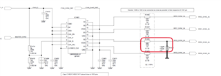
my circuit design as below for your reference; now the VDDO is 1v8, the Q2 connect with FPGA I/O via two resistors dividing voltage (because the FPGA I/O input voltage scope is 1V-1.8V) ,I want to keep the FPGA input voltage at about 1.2V.

my question is whether I can use the Q2 output in this way?

if no, please give your reason and other proposal.

 if yes, what is the current of case?   the Q2 current driver capability is enough or not?please help to calculate the values ,i don't find the output current parameter in datasheet.

  • Hi Wu,

    You can use the voltage divider to get to your required VOH levels on the output. R1410 can be brought down to 150 to get the closer values to 1.2 V taking into account the output impedance of the buffer which is 7 ohm.

    The current through the driver to output can be calculate  as below:

    Output current  = VDD / total impedance = 1.8 / (7+ 68 + 150) = 8 mA

    With your current config.

    Output current  = VDD / total impedance = 1.8 / (7+ 68 + 150) = 7.4 mA

    Best,

    Asim

  • HI Asim,

    "With your current config.

    Output current  = VDD / total impedance = 1.8 / (7+ 68 + 150) = 7.4 mA" 

     Please help confirm the information you reply,150?  I'm a little confused.

    Could you please inform the Q2 output current capability --Imax and Imin?

  • Hi Wu, 

    There is a typo in my previous answer, it should be 136 ohm that was used there. In your case it would be around 8.5mA. 

    it’s a CMOS output stage. Output impedance of driver is about 7 ohm so you can use that into your total path to calculate the current. 

    Best,

    Asim