This thread has been locked.

If you have a related question, please click the "Ask a related question" button in the top right corner. The newly created question will be automatically linked to this question.

LMK00804B: possible to drive 4 x 50 Ohm load?

Genius 12755 points
Part Number: LMK00804B
Other Parts Discussed in Thread: LMK00804

Hello Team,

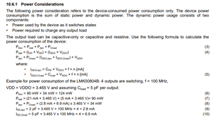
below picture represents a 50 Ohm load termination to VDDO/2, correct?

So I calculate current = VOH/93Ω = 2.6V/93Ω = 28mA. Doesn't this violate the IDDO Power Supply Current through VDDO of 5mA (Chapter 7.6 data sheet)?

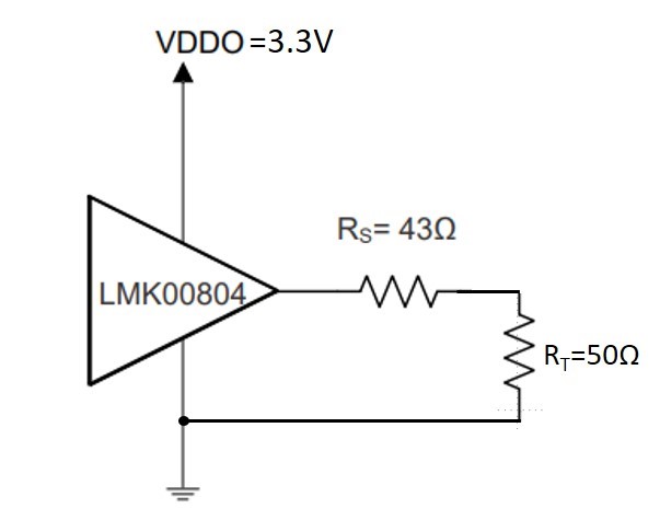
Can I use this buffer to drive 4 x 50Ω load (each output connected to 50Ω) terminated to ground (without the 43Ω in series)?

If yes, what levels can we expect?

Thank you and Best Regards, Hans

  • Hello Hans,

    I will get back to you by next week. However, I believe you can drive 4 outputs but still require a 43-Ω for each output to match the internal 7-Ω termination from the LMK00804. For the output levels,  how are you driving the outputs, via TTL or LVCMOS? Again, I will corroborate this and answer your other questions by next week. 

    Best,

    Andrea

  • Hi Andrea,

    output level should be adjustable (like LMK00804) between 1.5V and 3.3V. As far as I know TTL is 5V logic and not supported by LMK00804, correct?

    Thank you and Best Regards, Hans

  • Hans,

    • In regards to your current calculation, your math is correct.  The IDDO spec is misleading and incorrectly labeled.  It represents the static LVCMOS driver current. The current can go higher than the 5 mA shown.  28 mA is correct and will work.  In the datasheet at 10.6.1 there are examples that show current levels you are working with.  

    • The 43 ohm series resistor is required to sum with the output impedance listed at 7 ohms on the datasheet to get to 50 ohms.  This matches the transmission line impedance of 50 ohms.  If you fail to match the impedance your signal could contain reflections or overshoot.  

    • And yes, the LMK0804B output levels are adjustable (1.5V, 1.8 V, 2.5V, 3.3 V) and can support LV-TTL which is 3.3 V logic.

    Let me know if you need anymore clarification,

    Will

  • Hello Will,

    thank you for confirmation. Let's ignore reflections and overshoots due to mismatching. Would the device be able to drive 50 Ω directly (without the additional 43Ω) and provide a current of 2.6V/50Ω=52mA? Or, in case the IC limits the current what voltage level can we expect over the 50Ω for VDDO=3.3V?

    Thank you and Best Regards, Hans

  • Hans,

    Yes the device would be able to drive the 50 ohm directly.  Because the datasheet does not contain a max output current spec, given that the IDDO spec is incorrect.  We can check if your output current will function correctly by using formula for Junction Temperature  listed in section 11.1.2 on the datasheet.  

    Using the Power calculations formula from 10.6.1 using the maximum frequency of 350 MHz, and your maximum current 3.3/(50 Ω + 7 Ω output impedance) = 58 mA, and using a high ambient temperature of 70 degrees C.  Following the power calculations above and replacing the static IDDO of 5mA with your required current of 58 mA we can see that junction temperature stays under the maximum.  

    PDev = 273.73 mW + 117.63 mW = 391.36 mW
    Pstat = (21 mA × 3.465 V) + (58 mA × 3.465 V)= 273.73 mW
    Pdyn + PCload = (9.8 mA + 24.15 mA) x 3.465 V = 117.63 mW
    IDD,dyn = 2 pF × 3.465 V × 350 MHz × 4 = 9.8 mA
    IDD,Cload = 5 pF × 3.465 V x 350 MHz × 4 = 24.15 mA

    70 °C + (391.36 mW x 116 °C/W) = 115.39 °C < 125 °C

    So in the worst case, it is still under the recommended maximum Junction temperature, so it should work properly.  

    Thank you, and let me know if you have any further questions,

    Will