This thread has been locked.

If you have a related question, please click the "Ask a related question" button in the top right corner. The newly created question will be automatically linked to this question.

LMK1C1104: Recommended balun configuration

Part Number: LMK1C1104

Hi,

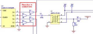
we would like to convert one of the outputs from the LMK to differential LVDS using a balun. Is it necessary to ac couple the buffer output like in the schematic below? Any other comments/recommendations to achieve this?

Thanks,

Joakim

  • Hello Joakim,

    We generally suggest to AC couple the outputs since that is the requirement for LVDS receivers. Therefore, AC coupling before the balun will be dependent on the input requirements of the balun. You probably want to AC couple after the balun for the LVDS receiver. Hope this helps.

    Good luck,

    Andrea

  • Hello Andrea,

    thanks for your reply. The LVDS receiver we're using typically want a non-zero common mode voltage so that's why we're biasing the center tap of the balun to 1.2V using a resistive divider. The balun is a pure trasnformer from Minicircuits and it seems to me to be important to AC couple the output from the LMK to avoid driving a large DC current into gnd. Clearly there are constraints on the output current that the LMK can deliver?

    On a related note: can the LMK swing from 0.2V to 2.8V (using VDD=3.3V) even when the load is 50 Ohms? Maintaining a logic high of 2.8V with a 50 Ohm load terminted to gnd gives a current of 56mA (2.8V/50Ohm). In the datasheet there are current comments of I_OH=1mA and I_OL=1mA for the 2.8V logic high output and 0.2V logic low output. If the current is the limitation the logic high voltage can only be 50mV when terminated to 50 Ohms. Is this correct or have I misunderstood the datasheet?

    In summary: what are the logic high and logic low levels when the output is terminated by 50 Ohms to gnd?

    Thanks,

    Joakim

  • Hello,

    I'll get back to you by next week.

    Best,

    Andrea

  • Hi Joakim, 

    Sorry for the delayed response. A typical LVCMOS receiver is high-impedance which is why the test condition for I_OH and I_OL is listed as 1 mA. However, the outputs of LMK1C can actually provide much more current than 1mA. The output impedance of LMK1C is around 50 Ohms, so if it is being terminated with a 50 Ohm load to GND the output swing will be reduced by around half due to a voltage divider effect. For example, with VDD = 3.3V the minimum value of VOH would be around 1.4V if connected to a 50 Ohm load. Let me know if you have any other questions. 

    Regards, 

    Connor