LMK3H0102: spread spectrum operation

Part Number: LMK3H0102
Other Parts Discussed in Thread: , USB2ANY

Tool/software:

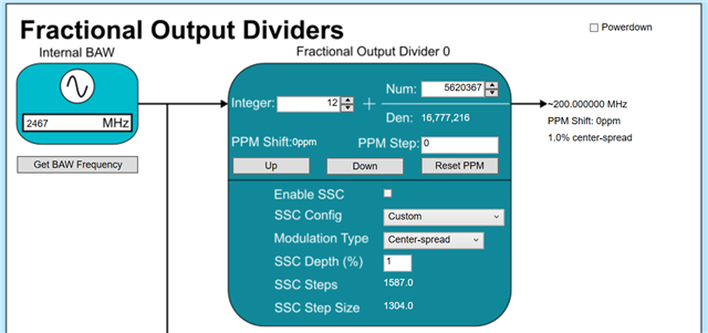
We are currently using the LMK3H0102 clk gen., and looking into spread spectrum. Specifically, we have three questions below:
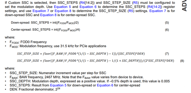
1) Do you have examples/instructions that demonstrate the steps in configuring the chip? i.e. actual register writes and sequence.  I see in the datasheet the relevant registers are R9, or R4&R5.  Are there any other ones?

2) For center spread, what is the starting phase of the SS modulation? Does it always start at the nominal frequency and go towards +ss% ?

3) We are interested in changing the output frequency during run-time.  How does this impact SSC modulation behavior and in particular, the phase (similar to question #2).  For example, I want to know if the SS modulation phase re-start at 0 deg. each time a divider (or some other config. that changes fout) is changed. 
  • Priscilla,

    1. My recommendation is to use TICS Pro for setting the spread spectrum values. If you enter the spread depth and specify the type of modulation (down-spread vs center-spread), TICS Pro will calculate the values of the SSC_STEPS and SSC_STEP_SIZE fields:

      The calculation is described in the datasheet with the fields to write:
    2. If SSC is disabled through the SSC_EN bit, then when it is re-enabled through this bit the SSC modulation will continue from where it left off (either increasing or decreasing). If the SSC is being enabled from the power-on reset state (either from OTP at startup or after toggle of the PDN bit), then the spread will start increasing.
    3. When changing the output frequency during run time, you must restart the spread algorithm by putting the part into power-down mode (PDN = 1), writing your new values, disabling OTP autoload (OTP_AUTOLOAD_DIS = 1), then bringing the part out of power-down mode (PDN = 0). The output clock will be disabled during the power-down mode. 

    Thanks,

    Kadeem

  • Hey Kadeem!

    Quick follow on question- if one of the FODs in table 7.5 from the datasheet (FOD Integer and Numerator Divide Locations) is changed during run time, what is the max settling time that can be expected? Say, for two cases:

    1. A) big step: something like ~20MHz change to ~30 MHz.
    2. B) small step: ~20MHz to ~21MHz.

    Thanks!
    Alisa Thomas

  • Alisa,

    Generally speaking, the change for the output frequency when changing FODx_N_DIV or FODx_NUM is within a few us from the I2C transaction. Part of this timing will be dependent upon the I2C host (as an example, the MSP430 functioning as a USB2ANY on the LMK3H0102EVM inserts ms of delay between each individual I2C transaction, so the full timing as seen on the EVM is ms rather than us).

    Thanks,
    Kadeem