This thread has been locked.

If you have a related question, please click the "Ask a related question" button in the top right corner. The newly created question will be automatically linked to this question.

LM555: [Consultation] LM555CMMX Function Check with my design

Part Number: LM555
Other Parts Discussed in Thread: TLC555, NE555

Tool/software:

Hi TI service team,

For LM555CMMX timer application in my system, I have questions about the functional operation want to consult with you.

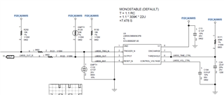
For my requirements, I want to add a timer with LM555 by RC delay calculation between TRIGGER_N pin to the OUTPUT pin, and I only need MONOSTABLE behavior without oscillator output status.

Therefore, I set R=309K*C=22uF delay in THRESHOLD pin for timing delay with about 7s (1.1*R*C).

How does the LM555 behave? Am my understanding correct with below descriptions?

If I'm wrong, please help to correct and give advice of right mechanism with this IC.

When TRIGGER_N is higher than 1/3*VCC, OUTPUT pin will go H after THRESHOLD charge capacitor up to 2/3*VCC (~7s). (???)

When TRIGGER_N is lower than 1/3*VCC, OUTPUT pin will go L after THRESHOLD discharge capacitor low to 2/3*VCC (~7s). (???)

  • Hi Paul,

    I made a simulation of your circuit in TINA using the model of the TLC555 in place of the LM555 to demonstrate the behavior of the timer in monostable mode. Below are the resulting output waveforms:

    LM555_Monostable.TSC

    As you can see in the Vout waveform, the output will stay high for 7.478 seconds after the device is triggered.

    1. When TRIGGER_N is lower than 1/3*VCC (4V), the OUTPUT pin will go HIGH, and the capacitor starts charging.
    2. When the capacitor charges to 2/3*VCC (8V) and TRIGGER_N is HIGH (above 1/3*VCC), the OUTPUT pin will go LOW, and the capacitor discharges back down to 0V.

    For more information on using a 555 timer in monostable mode, see this FAQ post: 

    [FAQ] How do I design monostable timer circuits using LMC555, TLC555, LM555, NA555, NE555, SA555, or SE555? - Clock & timing forum - Clock & timing - TI E2E support forums

    If you have any additional questions, please let me know.

    Best Regards,

    Alex Curtis

  • Hi Alex,

    So it will generate like Vout square-shaped waveform ((L --> H with about 7 seconds --> L)) continuously.

    Not like delay IC to generate fixed H signal after a period, and you should trigger L to it for assertion to L.

    Thanks.

  • Hello Paul,

    So it will generate like Vout square-shaped waveform ((L --> H with about 7 seconds --> L)) continuously.

    To clarify, Vout will stay low until the trigger pin is pulled low, since unlike astable mode where the output continuously alternates between high and low, the output is stable in the low state in monostable mode. If the device is triggered continuously, then the output will activate continuously.

    Not like delay IC to generate fixed H signal after a period, and you should trigger L to it for assertion to L.

    If trigger stays high, the output will stay low.

    Best Regards,

    Alex Curtis

  • Hi Alex,

    In our HW design, we just want to apply with timer delay function in our system, so we will only use monostable mode.

    From your statements, the LM555's function in summary seems like this:

    - If trigger pin stays HIGH, the Voutput will stay LOW

    - If trigger pin go LOWER than 1/3*VCC, the Voutput pin will go HIGH, and the capacitor starts charging

    Seems like Voutput won't stay HIGH in monostable mode, the Voutput pin can only keep with timer delay that we set in R/C, and capacitor charging is like a cyclic behavior when trigger pin stays LOW
    Am I correct with this understanding ?

  • Hey Paul,

    Yes Slight smile

    You are correct! From your response, it seems like you have a good understanding of monostable mode. If you have any other questions about 555 timers or need any additional assistance with your design, please let me know.

    Best Regards,

    Alex Curtis

  • Hi Alex,

    Thanks for your confirmation.

    I just want to further clarify the behavior when using LM555 in our system.

    Let's me describe some possible cases that we will encounter in system as below list: 

    Can you help to check with my understanding to LM555 of its performance ?

    "

    (1): If trigger pin go HIGHER than 1/3*VCC + stays HIGH, then Voutput will stay LOW

    (2-1): If trigger pin go LOWER than 1/3*VCC + stay LOW, the Voutput pin will go HIGH, and the capacitor starts charging, then Voutput will stay HIGH

    (2-2, continue with (2-1)): If trigger pin go HIGHER than 1/3*VCC + stay HIGH + capacitors charge above 2/3*VCC, the Voutput pin will go LOW, and the capacitor starts discharging back down to 0V, then Voutput will stay LOW (like case (1))

    (3) If trigger pin go LOWER than 1/3*VCC with a glitch (H->L->H), the Voutput pin will go HIGH (with timer delay that we set in R/C), and the capacitor starts charging

    "

  • Hello Paul,

    I'll address your statements one by one, and if you need clarification, feel free to reply and I can further explain my answers.

    1. Yes, correct.
    2.  
      1. Yes, the output will stay high until the capacitor charges above 2/3*VCC
      2. Yes.
    3. It depends on how long the trigger pin stays low. If the glitch (the length of time the trigger is low) is shorter than the minimum input length for the LM555 (roughly 1μs, see the table below) then the device should not trigger, and the output will stay low. If the glitch lasts longer than 1μs, the device should trigger and will follow the behavior you've described.

    (+) [FAQ] How do I design monostable timer circuits using LMC555, TLC555, LM555, NA555, NE555, SA555, or SE555? - Clock & timing forum - Clock & timing - TI E2E support forums

    Best Regards,

    Alex Curtis

  • Hi Alex,

    Most explanation really clear to me and let me understand this LM555 IC more details.

    I think I have a bit confusion in (2-1) If trigger pin go LOWER than 1/3*VCC + stay LOW, the Voutput pin will go HIGH, and the capacitor starts charging.

    I originally thought that Voutput voltage can stay HIGH if the status keep with (trigger pin go LOWER than 1/3*VCC + stay LOW).

    So it can't be possible and not only keep for a period of capacitor charging, right ?

    Thanks.

  • Hi Paul,

    Alex is currently out of office for the U.S. holiday. He will be able to provide a follow-up when he returns next week.

    Regards,

    Zach

  • Hi Paul,

    Thank you for your patience, and I apologize for the confusion.

    If the trigger pin stays low, the output will stay high. If the trigger pin is lower than 1/3*VCC when the timing capacitor charges to 2/3*VCC, the device will trigger again and the output will stay high. 

    Best Regards,

    Alex Curtis

  • Hi Alex,

    Got it, so it has condition that output will stay high if the trigger pin stays low (lower than 1/3*VCC and capacitor charge greater and equal than 2/3*VCC).

    So below waveform only occurs when Vtrigger give a low pulse instead of keeping a low state like I described previously.

    (before the end of the timing pulse --> need to go high before capacitor charge to 2/3*VCC, right?)

    Or it will retrigger the Vout pulse width, for example: if Vtrigger go high after timing pulse, it will retrigger the Vout pulse with 2times width, right?

  • Hi Paul,

    Yes, it's advisable to bring the trigger input high before the end of the output pulse to prevent unintentional retriggering. 

    Regarding the behavior of the threshold pin, we can take some measurements in the lab of an LM555, since the LM555 is the only device where threshold has pin priority over trigger. We should have something for you in about a week.

    Best,

    Alex Curtis

  • Hi Alex,

    We have Vout application with steady H state to end devices (for example: EN pin), so it might keep Vtrigger pin with L state and let Vthreshold start to charge capacitor over 2/3*VCC.

    So if it had function which can keep Vout with steady H state (with continuously retriggering), I'm ok with it.

    Thanks a lot.

  • Hi Paul, 

    The LM555 has threshold as the priority. If the trigger pin is not brought high before the timing capacitor is charged to 2/3 VCC then the output will go low briefly again. This is not easy to simulate however we did observe this in simulation and I have confirmed this behavior with our design team. All other timers such as NE555 TLC555 etc have trigger as the priority pin. 

    Best Regards, 

    Chris Featherstone

  • Hi Chris,

    Ok, thanks for your replies.

    I just wonder the behavior when Vtrigger pin turns back H timing is after the capacitor charging to 2/3*VCC, then what will Voutput pin react to this condition.

    Seems that Voutput pin will go low briefly in this case and back to H state, then it will keep doing 2nd capacitor charging time period.

    After 2nd time capacitor charging, Voutput pin will go L and capacitor will start to discharge back down to 0V.

    Am I correct with this understanding ?

  • Hi Paul, 

    Yes that is correct. 

    Best Regards, 

    Chris Featherstone