LMK05318B: : LOS_XO & LOS_REFERENCE

Part Number: LMK05318B

Tool/software:

Hi TI, 

I am currently using LMK05318B in our application design, having 

  • external TCXO with 40MHz
  • external PRIREF 25MHz

In principial this is working fine and I am getting a suitable lock.

When reading out the status registers, also everything is locked.

When reading out the interrupt registers, 

  • R19 bit0 (LOS_XO_INTR) is set, even after clearing it
  • R20 bit3 (REFSWITCH_INTR) is set, even after clearing it

I am guessing there is an intermitting and short term issue occuring, which is not visible at the status bits but visible at the interupt bits.

Looks like XO input and Priref input are not qualified as valid, for a short time.

Customer would like to confirm what is the mistake may cause this issue? can you help to check?

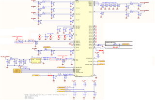
Please see attached tcs file.

forum.tcs

P.S: Running the same settings at the EVM board does not lead to this error and everything is working as expected.

Thanks & Regards

PF

  • Hi PF,

    1. It looks like you attached the register hex file (.txt) instead of the TICSPRO GUI files (.tcs). Can you please share the .tcs by going to File-> Save?
    2. Is it possible to probe the XO input (TCXO)? Perhaps it is shorting or the signal is unstable on the customer board. If the XO becomes invalid, then this will impact DPLL lock hence the REFSWITCH gets triggered. It looks like the device switches between holdover (XO) and DPLL lock (REF) since the XO is intermittently failing.
    3. Can you clarify what they see?
      1. Is it... power-up  -> clear interrupt -> wait some time -> readback interrupt -> XO INTR is 0 (passes)
      2. Or is it...power-up --> clear interrupt -> XO INTR fails -> clear interrupt -> XO INTR fails -> clear interrupt -> XO INTR fails (basically the XO intr toggles even though the live LOS_XO stays cleared.)

    Regards,

    Jennifer

  • Hi Jennifer, 

    thanks for your feedback. 

    1. I edited my original post and added the tcs file instead of the txt file.
    2. This is also my assumption. I have proped the TCXO signal and have not seen any issue. Additionally, I even used the signal from my application board and fed it into the XO_P of the EVM board and there this issue does not occur. This points me in the direction of some issue with LMK on my board or surrouding components.
    3. after powerup, I clear the interrupt sources and directly read it back. XO_INTR is always 1. Actually I have never seen this interrupt register being 0. This statement, describes it pretty well from your side: "basically the XO intr toggles even though the live LOS_XO stays cleared "

    When checking the OUT6 CLK, this "looks" all the time locked to the PRIREF input.

    It seems like this short time LOS_XO leads to a very short holdover event, which is not long enough to qualify for an unlocked event.

    Br, PF

  • HI PF,

    1. I tested the .tcs file with a signal generator as an XO input to the LMK05318BEVM. I do not see the LOS_XO_INTR toggle. 
    2. When you feed the XO_P to the EVM board, does the EVM use the same supply as your application board? Essentially, the EVM should be configured to "DIRECT VIN/VDD" to bypass the on-board LDOs.
    3. Is it possible to probe the XO power supply? Maybe the XO supply is unstable.
    4. Is the LOS_FDET_XO_INTR also toggling?

    Regards,

    Jennifer

  • Hi Jennifer,

    1. Thanks for verifying 
    2. I used the onboard LDO from the EVM and supplied it by 5V. I will test to feed directly 3V3 from my application board to the EVM and bypass the LDOs.
    3. Do you mean the supply for the external TCXO or the VDD_XO supply pin for the LMK? I changed from 3V3 to a clean 1V8 supply from an onboard LDO and still the same result, is there a limit for the voltage tolerance? Additional questions, is there a way to change to monitors which qualify the XO CLK as valid?
    4. No, this bit is not set.

    Some further tests. 

    • Supplying the clean 3V3 (after the LDO) from the laboratory power supply to the application shows the same error
    • supplying the XO from the EVM to the application board shows the same issue

    Just measured the spectral noise density of the 3V3_SMPS rail (yellow) vs the 1V8_LIN rail (oraneg &supply for TCXO) 

    Also measured the spectral noise density of the 3V3_SMPS rail (yellow) vs the 3V3_SMPS_Bead rail (orange & supply for LMK) 

  • Hi PF,

    1. "Do you mean the supply for the external TCXO or the VDD_XO supply pin for the LMK? I changed from 3V3 to a clean 1V8 supply from an onboard LDO and still the same result, is there a limit for the voltage tolerance?"
      1. I meant powering the supply of the TCXO VDD. The VDD_XO from the LMK requires 3.3V.
    2. "Additional questions, is there a way to change to monitors which qualify the XO CLK as valid?
      1. No, it is not possible to change the settings for the XO. However, since you say that the XO FDET does not get set, this could possibly point to it being a swing issue. Can you probe and send a scope capture of the XO_IN pin to see what the LMK receives.
    3. Do you have another application board with this problem? I'm wondering if perhaps the LMK on the application board could have have been soldered improperly. Is it possible to check with a new LMK chip?
    4. Regarding the spectral noise density plots, I'm not considered about the noise on the power supply for the LMK as it has excellent PSNR performance due to the integrated LDOs on the supply pins. I would be more considered about the XO as they usually are noise sensitive due to the lack of the internal LDOs on the supply pin. May you please clarify what instrument was used to capture these spectral noise plots?

    Regards,

    Jennifer

  • Hi Jennifer, 

    1. & 4. Today, I supplied the onboard TCXO on my application board with the Supply from the EVM LDO, with the same bad result. In this case the supply should be very clean. The measurement instrument is E5055A.
    2. Scope plot is attached. Measuring with an active probe and TCXO is supplied by 3V3 and LMK is currently internal terminated with 50R (no termination with a voltage divider leads to the same missing XO result)
    3. Most of our boards have this issue, some have LOS_APPL1 set but LOS_XO not.

    What is wondering me the most, even when using all supply rails from the EVM and the TXCO from the EVM and feed all of this to the application board, the LOS_XO bit gets set.

    One furher observation which is weird.

    When I read out R19 = 0000 1001 (LoS_XO & LOL_APLL2 (deactivated))

    Now I modified R17 = 0001 1101  -> 0000 0000 (This should change the polarity of the Interrupt Register R19)

    Reading out R19 again (and clearing it beforehand) = 0001 0101 (This would mean only LOL_APLL2 is set now)

    EDIT: In the meanwhile i found one board out of 20, where the LOS_XO bit is not set and everything is running as expected, but this situation only occurs after 15-20min and is very hard to reproduce and only after a restart. Not sure what could lead to this situation.

  • Hi PF,

    1. Thank you for clarifying the instrument used to capture the data. I don't see issues with the power supply being the cause at this time.
    2. The plot you shared is probing at the XO_IN pin of the LMK?
    3. Can you attach the LMK05318B schematic used?

    Regards,

    Jennifer

  • Hi Jennifer,

    yes the plots are directly probed at the XO_P input.

    Please see attached schematic.

  • Hi PF,

    I'm not seeing anything glaringly wrong with the schematic either.

    Can you provide the start-up scope plots of the PDN, 3V3 and 1V8 rails? I want to make sure the ramp timing is occurring properly.

    Regards,

    Jennifer