This thread has been locked.

If you have a related question, please click the "Ask a related question" button in the top right corner. The newly created question will be automatically linked to this question.

LMK04832: Advice on Link Jitter and LMK on chip compensation mechanism

Part Number: LMK04832
Other Parts Discussed in Thread: LMK1D1204, LMKDB1102, SN65LVDS32, LMK1D1204P, LMK1D2102

Tool/software:

Dear Exprts,
Need some advice below:
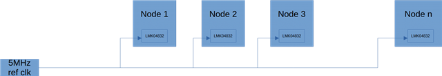
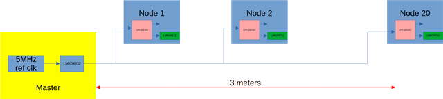
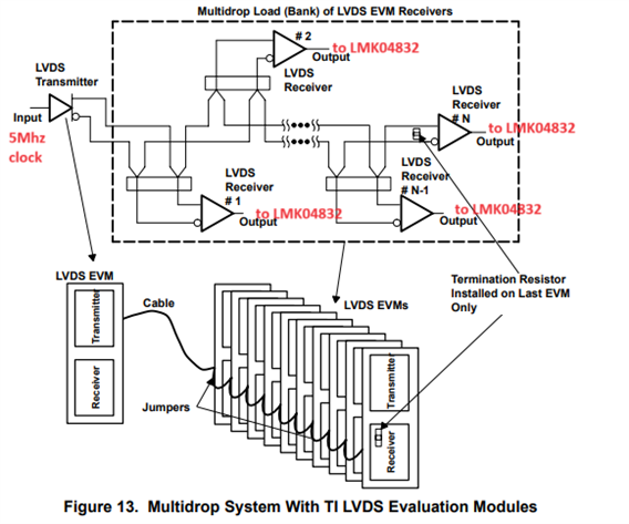
Referenced to TI’s below app note, figure 13, we are planning to use the below multidrop topology to carry a 5Mhz reference clock to up to 6 nodes within 3 meters.  
Each node will equip one LMK04832 for multi-node synchronization purpose, and the 5Mhz will act as their reference clock.
Would like to check with you whether the link jitter will be a concern and whether the LMK on chip compensation mechanism is able to address the concern?
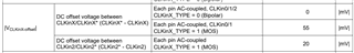
The physical electrical interface we are considering are M-LVDS and RS485.
Any advice? 
Best regards,
Felix
  • Felix,

    I'll get back to you by the end of the week.

    Best,

    Andrea

  • Felix,

    At a high level, based on the results they are showing, I would recommend to not split the LVDS driver into 4 lines to feed the LMK04832. Instead, I would recommend to use the LMK1D1204 to properly copy this input signal into the LMK04832s. Why have you not considered using a buffer?

    If you choose to note use a buffer, the main thing to worry about is ensuring the input signal meets the input requirements of the LMK04832. Note that the LMK04832 does not have solely an LVDS input receiver, instead it is universal and can accept several different types of signals. Also, you need to ensure the P and the N waveforms reach the LMK04832 at the same time so the signal is properly handled by the LMK04832.

    Slew rate requirements:

    Voltage swing:

    Voltage CLKin Offset:

    Hope this helps.

    Best,

    Andrea

  • Thanks Felix for relaying the question.

    Thanks Andrea for the reply. We did consider adding a buffer before. However, some of the nodes are designed to be power off as required. We are afraid that the buffer output will be clamped by the protection diode on the unpowered device. Therefore we consider this multi drop topology. 

    HR

  • Zhu,

    Can you give me a schematic or block diagram so we can better see which nodes are being powered off and better understand why this might affect our devices. Also, we have fail-safe input LVDS buffer that might work for your application: LMK1D120x.

    Best,

    Andrea

  • Hi, Andrea,

    Attached is the use scenario. The master reference clock is passed down in a cascaded manner. 

    The clock is supposed to pass to all the 'powered on' nodes in the chain even if any of the nodes is powered off.

    If we are to use a buffer chip, we are afraid that the clock swing will be clamped by the protection diode in any of the 'powered off' nodes. 

    Thanks. 

  • Zhu,

    I'm talking to my design team to better understand if this would be ok with our buffer. I should be able to get back to you by Monday.

    Best,

    Andrea

  • Zhu,

    What's the drive strength of the 5MHz input?

  • Hi Andrea,

    The current idea is to use one LMK04832 output to provide the 5Mhz clock.

  • Zhu,

    So do you have 5 LMK04832 in your system? If so, what is driving the first LMK04832? An LMK04832 will always need a reference to work properly.

    Regardless, I got some answers from design. The LMK04832 inputs are not failsafe (ESD diode to VDD33), so they will clamp and reduce the swing/VOS (if they are shorting together the CLKIN on multiple LMK04832 instead of separating the 4 CLKIN). You will need a fail safe LVDS RX/buffer (LMK1DXX, SN65LVDS32 per the app note only has LVTTL outputs) at each node to protect the LMK04832 and not affect the single 5MHz input. Therefore, you could use the LMK1D1204P which has individual OEs for each output. You could also use an individual LMKDB1102 for each node if you don't want to control the OEs of the LMK1D based on which cards are powered up, but this would be bigger in size and more costly.

    Best,

    Andrea

  • Hi Andrea,

    We will have one master board and about 20 slaves installed at a separation of 15cm between each slave board. 

    Each of the node is powered individually. 

    Am I right to say that the devices you recommend, e.g LMK1DXX LMK1D1204P are all failsafe (even not powered, their inputs will not be clamped)?

    Thanks.

  • Hi, Andrea,

    I updated the block diagram to capture your proposal. Can you please help to confirm? Thanks. 

  • Zhu,

    Correct the LMK1D has fail-safe inputs. Also, are you just using the LMK04832 as a buffer? What's the purpose of placing a LMK04832 to give the input signal to the different nodes?

    Best,

    Andrea

  • Hi, Andrea,

        The clock transmitter module is designed by the end customer, and the block diagram is as given. Probably the LMK04832 is to synchronize another set of nodes?

        Is there any concern to use LVDS signaling across 3 meters distance in our setup? The physical connection will likely be some Samtec wire to board cable assembly. 

        Thanks. 

  • Zhu,

    Having a 3 meter cable will lower the amplitude of the LVDS signal and cause more reflections from the transmission line. Please use the .ibs models on both products pages (LMK04832 and LMK1D2102) to determine the correct series resistance values needed to eliminate any ringing that may come from this long transmission line. Note that this Rs added to mitigate any reflections will further decrease the amplitude of the LMK1D outputs into the LMK04832. While the input amplitude and slew rate specs are met of the LMK04832, there should be no problems with the 3 meter long transmission line.

    Also, if you are not using coaxial cable/shielded cable, there may be some jitter added to your system. If so, I would recommend to use the LMK04832 as a jitter cleaner (add an external VCXO to each LMK04832 at the different nodes), to clean your input signal and continue propagating a clean clock through your system.

    Best,

    Andrea