This thread has been locked.

If you have a related question, please click the "Ask a related question" button in the top right corner. The newly created question will be automatically linked to this question.

LMK5C22212A: Design Query

Part Number: LMK5C22212A
Other Parts Discussed in Thread: LMK1C1103A, , LMK5C33216, LMK5C23208A

Hi Team,

I'm planning to use the clock generator LMK5C22212ARGCT  in my design. Please address the below queries. The clock generator outputs are given to ADCs, 

Below is the current design clock architecture 

image.png

  1. In the current design, separate 32.768 MHz clock signals are provided to three different ADCs. However, the design requirement is that all ADCs on the board must operate in synchronization.
  2. For achieving synchronization, should the same clock output be distributed to all three ADCs, or can different clock outputs be used as in the current approach?
  3. If three different clock outputs are used, please confirm whether OUT0_P, OUT0_N, and OUT1_P are derived from the same internal VCO of the clock generator or from different VCOs.
  4. I am sharing two possible ADC clock architecture approaches. Please suggest which approach should be used to ensure proper synchronization of all three ADCs with respect to the provided MCLK.ADC MCLK flow.pptx 

Regards,

Abhishek

  • Hi Team,

    Also, since the same 32.768 MHz CMOS clock is routed simultaneously to all three ADCs, there is a possibility of trace stubs in the clock routing. Is it recommended to use a clock buffer in the clock distribution chain, or how should this be managed in the design?

    Regards,

    Abhishek

  • Hi Abhishek,

    We're currently investigating your queries, I'll get back to you early next week.

    Best,

    Jaryd

  • Hi  Jaryd,

    Please address the query at the earliest as it is critical for my design confirmation.

    Regards,

    Abhishek 

  • Hi Abhishek,

    I'll answer your questions below:

    1. To synchronize all 3 ADCs, you shouldn't need a buffer as long as the outputs are synced. On TICS Pro under the "SYNC/SYSREF/1-PPS" tab, you can sync OUT_0 and OUT_1 outputs by checking the "OUT_0_1_DIV_SYNC_EN" box on the GUI. This ensures OUT_0 and OUT_1 have the same rise/fall times. This is also configurable via register settings (R969 bit 5).
    2. You can set OUT0_P, OUT0_N, and OUT1_P to be derived from the same internal VCO via the TICS Pro GUI by setting the output source of OUT0 and OUT1 to "PLL1".
    3. Based on the above commentary, Approach 2 in your slide deck is sufficient to properly synchronize the ADCs.
    4. A clock buffer in the clock distribution chain shouldn't be necessary. Do you have strict skew requirements? If 80ps output skew is sufficient, then a clock buffer is not necessary.

    Additionally I noticed you are inputting single-ended clock signals into the ADCs, and if you use both ends of OUT_0 the clocks will be 180° out of phase. If you need these two outputs in-phase, you'll need to invert one end of the signal as shown below (in the outputs page of TICS Pro GUI). You can double-check these outputs with an oscilloscope to verify. If 180° out of phase is ok for your application, you can ignore this.

    Best,
    Jaryd

  • Hi Jaryd,

    Thanks for the reply.

    In my board for the ADC AD7768, the same CMOS clock of 32.768MHz to be given to all the 3 ADCs in my board. For that purpose, I'm planning to use the clock buffer LMK1C1103APWR. Is this clock buffer is good for my application.

    From the OUT0P I'm planning to give the 32.768MHz CMOS output to the clock buffer.

    Regards,

    Abhishek

  • Hi Abhishek,

    Yes, the LMK1C1103A is a good low-jitter and low-skew option for your application for fanning-out a single output from OUT0_P. 

    Best, 
    Jaryd

  • Hi Jaryd,

    Please find the attached schematics for the clock circuit. Please review and provide your feedback.

    Please confirm whether the output channels can be connected are okay.

    For the clock buffer, two input options are provided

    1. From FPGA a 1V8 CMOS clock of 32.768MHz is provided as input to the buffer --- It is chosen as default.

    2. Clock OUT0_P clock from the clock generator is given to buffer input as optional --- In this case the clock generator output is 3.3V and buffer voltage is 1.8V( as 1.8V is needed for ADC), how should i level translate the 3.3V clock into 1.8V. Please recommend the level translator for this.

    Regards,

    Abhishek

  • Hi Jaryd,

    Sorry for the above comment as the schemaics are not attached.

    Please find the attached schematics for the clock circuit. Please review and provide your feedback.

    Clock circuit.pdf

    Please confirm whether the output channels can be connected are okay.

    For the clock buffer, two input options are provided

    1. From FPGA a 1V8 CMOS clock of 32.768MHz is provided as input to the buffer --- It is chosen as default.

    2. Clock OUT0_P clock from the clock generator is given to buffer input as optional --- In this case the clock generator output is 3.3V and buffer voltage is 1.8V( as 1.8V is needed for ADC), how should i level translate the 3.3V clock into 1.8V. Please recommend the level translator for this.

    Regards,

    Abhishek

  • Hi Abhishek,

    Regarding the schematic for your clock circuit:

    • The output channel connections look ok.
    • The LMK5C22212A supports 1.8V LVCMOS on OUT0, so you shouldn't need a level translator.
    • The external loop filter capacitor LF1 (C1686) should be 470nF.
    • The CAP_DIG capacitor (C1684) should be 10µF. There is a small typo in the LMK5C22212A datasheet, I'll bring this up so it can be fixed in the next datasheet version. For now, refer to the LMK5C33216 datasheet for this recommended capacitor value.
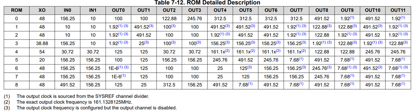
    • Are you using EEPROM to load your config? Your GPIO0 and GPIO2 appear to be configured to select ROM page 6. If you're using EEPROM then this doesn't matter, but if not then the clock frequencies below will output based on the ROM page.


    Best,
    Jaryd

  • Hi Jaryd,

    Thanks for the feedback.

    1.For 1.8V LVCMOS on OUT0, whether the VDD_ for OUT0 need to be connected to 1.8V or TICS pro tool can change the output to 1.8V?

    2.I want to configure or control the SOM through the SPI interface connected to the FPGA via the CS, SCLK and SDATA signals. Whether any circuit changes need to be done for this configuration.

    3.Layout here will be critical to confirm we get proper clock signaling. Board to board connectors could increase capacitance on the clocking line or have other unintended effects. how it can be mitigated in layout. Any layout recommendations or suggestions for this?

    Regards,

    Abhishek

  • Hi Abhishek,

    To answer your questions:

    1. You can configure the output format of OUT0 to 1.8V LVCMOS through TICS Pro on the start page or outputs page.
    2. The LMK5C is fully programmable through SPI. You would just need to ensure there are physical connections for the SDIO, SCK, and SCS_ADD pins from the LMK5C to the FPGA. Setting GPIO1 = 1 during POR enables selection of SPI on startup. If you're using a 4-wire SPI configuration, then setting SPI_3WIRE_DIS = 1 allows any GPIO to be selected as SDO to support readback with 4-wire SPI.
    3. In general, you can reduce the effects of clocking line capacitance by minimizing trace lengths and using low-capacitance connectors. If you'd like to model the effects of capacitance on your clocking lines, we have IBIS models on ti.com that can be used for signal integrity simulation for this part.

    Best,
    Jaryd

  • Hi Jaryd,

    For the clock buffer LMK1C1103A does it has any voltage drift. Because the output needs to be fed to high precision ADCs.

    Regards,

    Abhishek

  • Hi Abhishek,

    The buffer shouldn't have any voltage drift.

    Best,
    Jaryd

  • Hi Jaryd,

    As i have shared my clock tree some of the outputs are not used. 

    1. Is there any alternate part available for me with less outputs, which has jitter less than 100fs. I need 7 LVDS output and 1 CMOS output as i mentioned in the shared in the updated clock tree

    EMFT0-01 Clock Tree.pptx

    2. Is for low noise and jitter applications as in my case it is medical also, while connected the adjust channels does it cause any jitter or any other issues.

    3. For LMK5C22212ARGCT, what is total supply voltage current consumption.

    Regards,

    Abhishek

  • Hi Abhishek,

    I will get back to you regarding your frequency plan, as it seems like it will be difficult to implement the 125MHz and 27MHz outputs without using a buffer to fanout the 100MHz outputs. This is because the LMK5C has a limited amount of APLL1 outputs, which are needed because its VCO frequency range enables both 100MHz and 125MHz outputs from the same APLL. For now, I'll answer your questions below:

    1. We do have the LMK5C23208A as an alternate part, which has 8 outputs, supports LVDS outputs and LVCMOS on OUT0 and OUT1, and has <100fs RMS jitter for BAW APLL outputs. However the typical RMS jitter does exceed 100fs for the APLL1 and APLL2 outputs. 
    2. We have typical phase noise curves in the datasheet section 5.7, which detail the noise and jitter for different APLLs and output frequencies. These characteristics are similar on all outputs of the device.
    3. The total current consumption of the LMK5C22212A depends on the configuration. Per the datasheet, here is information on the device current consumption for different configs:

    Best,
    Jaryd

  • Hi Jaryd,

    Please check and confirm the frequency plan, for using the clock generators LMK5C22212ARGCT and  LMK5C23208A , so that can check the possibilities for using these two clocks generators.

    Regards,

    Abhishek

  • Hi Jaryd,

    Any updates on above query.

    Regards,

    Abhishek

  • Hi Abhishek,

    Regarding your current configuration, would you be able to tell us a bit more about your requirements? Specifically:

    • The RMS jitter limits specified in the datasheet depend on your output frequency. Is the 100fs jitter specification a hard limit for all outputs? Which output frequencies is this limit for? We don't currently have a jitter specification for 32.768MHz for either the LMK5C22212A or the LMK23208A.
    • Are you able to buffer the 100MHz outputs to fanout this frequency? The LMK1D1208 is a differential buffer that supports LVDS for your 100MHz outputs. Using this along with the LMK5C23208A should allow your frequency plan to work.

    Based on your responses, we can adjust our recommendations for your frequency plan implementation.

    Best,
    Jaryd

  • Hi Jaryd,

    • The 100 fs jitter specification is a system-level requirement. Some parameters can be adjusted; however, the 32.768 MHz clock must be maintained as is, while the remaining outputs are intended for digital interfaces.
    • Adding an additional buffer for the 100 MHz outputs is not preferred, as the 32.768 MHz clock is already buffered using LMK1C1103APWR. Introducing another buffer stage in the clock path is not desirable.
    • Could you please review and suggest an optimized frequency plan, including channel allocation, for LMK5C22212ARGCT and LMK5C23208A? If feasible, using the 8-channel LMK5C23208A would be preferred to avoid unused channels in the 12-channel device

    Please provide the frequency plan with both clock generator with minimal possible jitter.

    Regards,

    Abhishek

  • Hi Jaryd,

    Any updates on above.

    As for LMK5C23208ARGCR what is the maximum supply current consumption (3.3V).

    Regards,

    Abhishek

  • Hi Abhishek,
    The current consumption depends on the configuration, the enabled outputs and dividers...
    It has to be calculated and verified in development.

    Refer to datasheet LMK5C23208A SNAS918 – MAY 2025
    6.5 Electrical Characteristics


    Regards,
    Octo

  • Hi Abhishek,

    The 100fs RMS jitter requirement for all outputs will be difficult to achieve with one device. The LMK5C23208A datasheet specs 12kHz - 20MHz RMS jitter for a variety of output frequencies, but unless you use APLL3 (BAW APLL) for all outputs the jitter will be higher than 100fs. And even this is not guaranteed for the 32.768MHz output since this condition was not tested for in the datasheet. Using a free-running oscillator such as the LMK6D for the 27MHz output would free up one of the PLLs, have less crosstalk, and be a cheaper/simpler implementation; however, the datasheet specs the RMS jitter for 100MHz at a typical value of 140fs. 

    With jitter aside and purely looking at your frequency plan, the frequency domains that your outputs occupy require more PLLs than the LMK5C22212A or LMK5C23208A offers. For example, the frequency range of VCO2 is 5595MHz - 5950MHz which cannot divide into 100MHz, 125MHz, and 27MHz evenly. The frequency plan is possible if the 100MHz and 125MHz are sourced from PLL1 and the 27MHz is sourced from PLL2, but there are not enough PLL1 outputs to support 5 100MHz outputs and would require a buffer to fanout these outputs. This is the main reason I suggested to include a buffer or free-running oscillator in your design for the extra output frequencies.

    I can run a few spot checks on a LMK5C EVM in our lab if you'd like to confirm the jitter you can expect for the frequencies in your design. However based on the specifications in the datasheet it is very unlikely to have all outputs at or under 100fs RMS jitter. For APLL1 we can expect to see roughly 200fs of RMS jitter from the outputs. 

    So bottom line, for your design to achieve ~100fs RMS jitter on all outputs, you will most likely need multiple DPLL devices with BAW. The buffer or oscillator additions would work for a more relaxed RMS jitter requirement and would have comparatively lower BOM costs, but this largely depends on what jitter you're able to accept for each output.

    Best,
    Jaryd