This thread has been locked.

If you have a related question, please click the "Ask a related question" button in the top right corner. The newly created question will be automatically linked to this question.

TLC555: 10us minimum one shot time

Part Number: TLC555
Other Parts Discussed in Thread: NE555

In the newest datasheet for the TLC555 (SLFS043H), on page 10 it states:

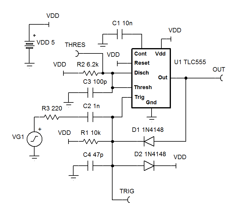
When the trigger is grounded, the comparator storage time can be as long as 10 μs, which limits the minimum monostable pulse
width to 10 μs.

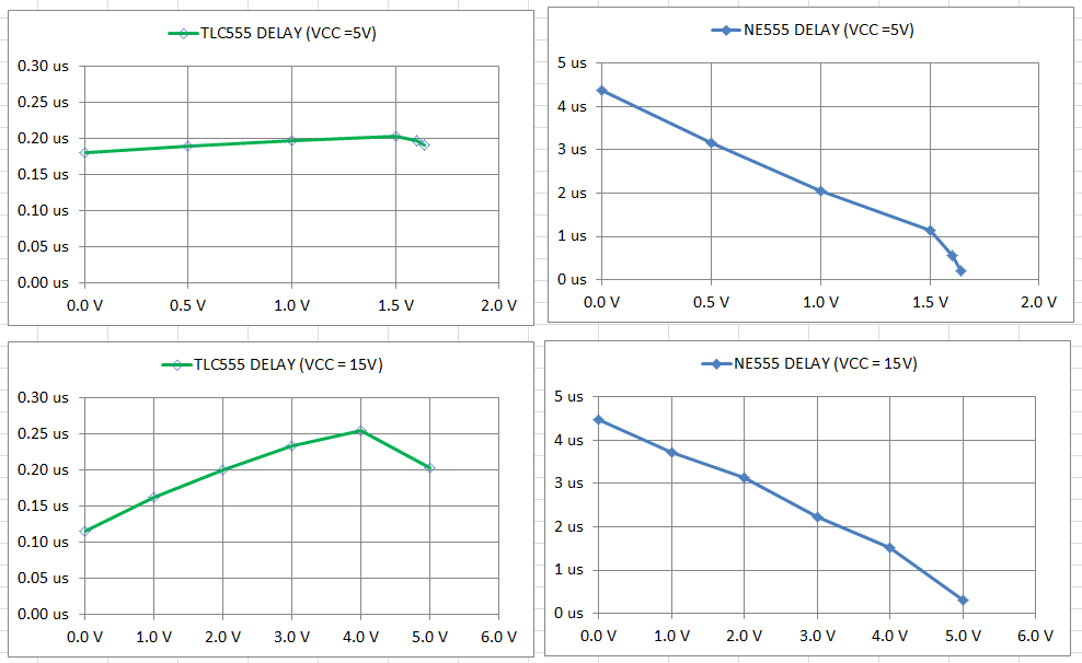
Obviously, the astable operation cannot reach 2MHz with this 10us limitation, so my understanding is this delay is not evident when the trigger voltage is 1/3 of Vcc.  A graph of trigger voltage vs. delay would be most helpful.  If the CONT pin is used to lower the trigger voltage, at what point does this comparator storage time start to show up?   Also, earlier datasheets don't mention this problem.  Is this because it was only recently discovered, or was this problem created by a die modification (die shrink)?

Thanks,

Dave G.

  • David,

    The trigger pulse need to be long enough to reliably trigger, yet short enough to disengage fully before the end of charge to threshold level. The reason is that TRIG has priority over THRESHOLD. Therefore there are two limiting factors. What is your desired input pulse width and desired output pulse width?
  • David,

    VCC is also important. Your Vcc is?
  • David,

    This simulation provides a 1us one shot. This hasn't been bench verified.

    Input is AC coupled so it can be set low indefinitely.

    One diode limits overshoot on trigger when input goes high the other diode pulls trigger high when output goes high to release trigger as soon as possible. The 47pF prevents output going low to AC couple via the diode causing a false re-trigger chance.

    TLC555 1us one shot (AC coupled input).TSC

  • Ron,

    Thank you for your replies.  But, I am still not clear on the statement in the datasheet about the 10us minimum pulse.  According to this statement, the 1us one shot won't work if the trigger signal is driven all the way to ground.  This is a very important "detail" that deserves move than a 2 sentence glossing over buried in the datasheet.


    Thanks,

    Dave

  • David,

    I will run some minimum time tests in the lab today.
  • Hi Ron,

    Thanks.  I assume when this issue with the chip was discovered, someone at TI characterized it by measuring a bunch of chips.  It's too bad that data was not put in the datasheet as a useful graph of trigger voltage level vs. comparator delay, and even worse the data isn't available to you and now you have to re-measure it.

    Thanks,

    Dave

  • David,

    The story is far different that you surmised.  This all started in the early 1970's. The person who discovered it is a very old person, maybe even passed away. No; there wasn't a TLC555 timer back then, but there was a NE555 timer. This timer has about a 5us storage time which is conservatively stated as 10 us requirement. This is fine for a 100 kHz max timer.

    Let's jump ahead  many decades in time to last August (insert time travel sound effect here). The TLC555 was updated to the new more informative data sheet standard. The person who did that probably noticed that the similar NE555 was already in the new format so it was easy to copy and paste sections from one data sheet to the other. By now you should know where I am going with this. The 10 us claim was copied from the NE555 datasheet.

    Because TLC555 is a faster version in a different  process and uses CMOS instead of bipolar transistors, it is unreasonable to assume both devices would have the same storage times.

    Here are my test results from this morning. I verified VIL (X axis) and recorded time ( Y axis) from trigger de-assertion to output falling edge. Threshold tied to VCC.

  • HI Ron,

    That's great news! Thanks so much for doing all that. The perils of "cut and paste" - that is often the cause of my firmware bugs :)
    When I saw that sentence in the datasheet, I was baffled. I had a copy of a 2001 version of the datasheet buried on my hard drive and compared, and there was no mention of such a thing.

    BTW, I am one of those old guys. I was in high school when the NE555 came out and the 741 opamp. I remember being so amazed. "You mean there are 22 transistors inside that tiny TO-5 can?" Now there are billion of transistors on a single chip. It is encouraging to see there are diligent engineers like you to carry the torch who will be persistent enough to get to the bottom of a problem!

    Thanks again!

    Dave
  • David,

    A little more research found that 10 us delay in NE555 data sheet was added in June 2010 (Rev H data sheet). So for 37 years, it was undocumented. Better late than never.
  • Hi Ron,

    I thought I would share with you a rather unusual application for the TLC555 I came up with I think in the 1990's, if I remember correctly.  It is a switching current regulator, designed to operate a 12VDC relay coil directly from the 120 volt line.  This was a first developed for a commercial coffee grinder timer that was very cost sensitive.  The grinder had a 1/2 HP motor, and the most cost effective relay with a UL motor rating was the Potter & Brumfield T90 series.  But, it didn't come in 120VAC coil version.  Adding a 12V transformer was too expensive.  I started thinking about making a cheap switching supply and about the inductor it would need, and wondered if it would be possible to use the relay coil as the inductor, which led to this design.

    This is a constant off time, variable on time regulator.  The off time is determined by C2, R6, and R2.  The on time is determined by when the current in the relay coil builds up to the threshold.  In order to reduce power dissipation n the current sense resistor, R5, R1 is used to pull the threshold and trigger voltages as low as you dare.  This is why I was concerned about low trigger voltage levels causing an additional 10us delay.  R4 and C1 are there so a current spike when T1 turns on, caused by D6 reverse recovery or the relay coil inter-winding capacitance (C3) won't cause a premature turn off of the on cycle.  This circuit is a bit simplified.  The 10 volts to power the TLC555 came from a resistor and zener off the line voltage bus.  Also, a movistor is essential to keep T1 from getting blown out by the nasty voltage spikes when the relay contacts open, especially with a motor load.  The relay is turned on and off using the reset pin of the 555.  This was connected to a 4541 timer chip.

    Just thought this might interest you.

    Dave

    tlc555-2.TSC