This thread has been locked.

If you have a related question, please click the "Ask a related question" button in the top right corner. The newly created question will be automatically linked to this question.

LMX2594: the curve about output level is strange

Part Number: LMX2594

Hi guys,

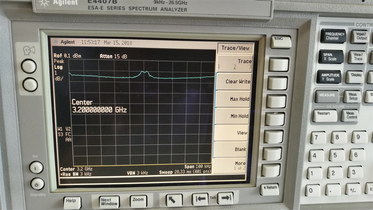
I found the curve about LMX2594 output level is very strange :

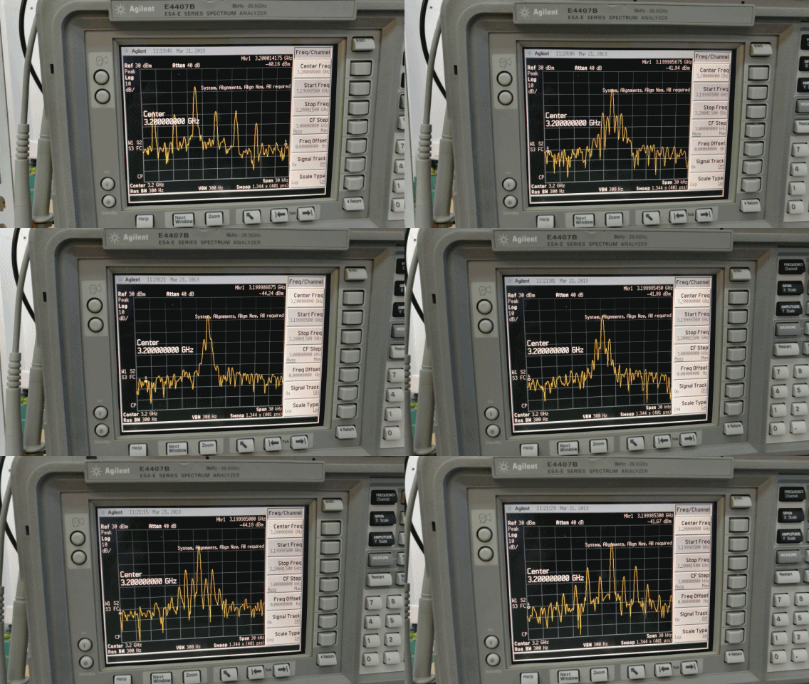
As you can see, the level is not stable around frequency 3.2GHZ when the span is 100KHZ.

Infact, this happened at frequency 3120,3140,3160,3180MHz...(every 20MHz).

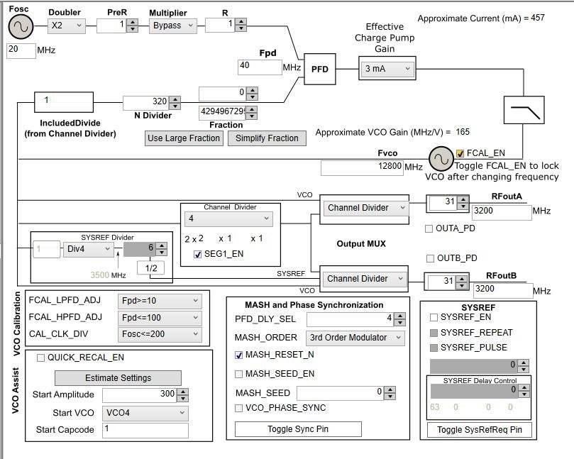
This is configuration about LMX2594:

What i have tried ?

1. Change "Effective Charge Pump Gain"

2. Change input Double,PreR,Multiplier,PostR

3. Change XTAL which output is sine wave  to square wave.

3. Change loop filter.

But this issue is still happen.

Is there something wrong ? How to fix this problem? 

Thanks!

  • Hello,
    Thanks for positing your issue on E2E. An expert has been notified and will get back to you very soon.
    Best regards
    Puneet
  • Hi KcMeter,

    Your configuration is all right and you should get a single tone in the spectrum analyzer. I don't quite understand your problem, could you make the ResBW smaller at this span? Also make the span wider, say 5MHz or 10MHz or 100MHz so that we can have a bigger picture to see how does your output look like?
  • Hi Fung,

    I'm sorry to confused you.

    My issue is:

    I think the LMX2594 output level will hold as a straight line at this straitness span.

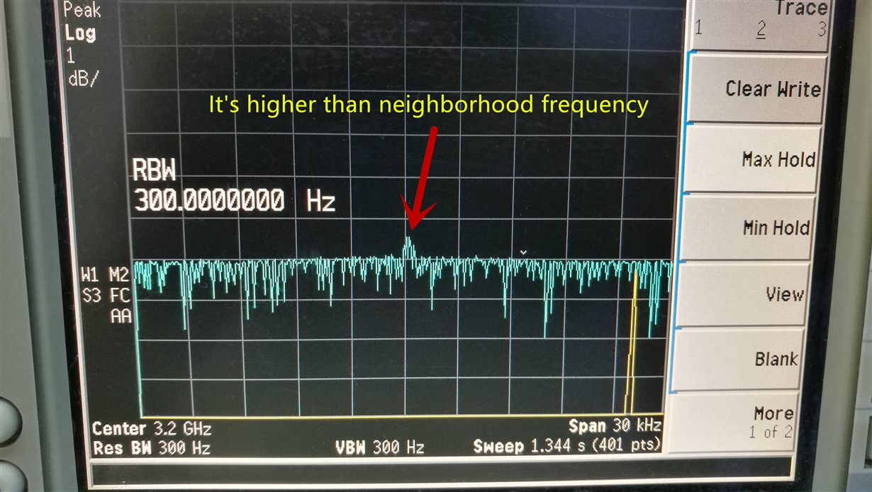
    In fact at center frequency is higher than neighborhood frequency(Maybe there is something wrong which is influence output level at frequency 3.2GHz).

    And I use smaller RBW to trace again:

  • Hi KcMeter,

    I still don't understand your question. Unless you use zero span, otherwise you should see a tone instead of a flat spectrum.

    here is my screen shot.

  • I'm sorry,I forgot to tell you that the picture which I displayed is use LMX2594 to sweep frequency 3199.985000MHz ~ 3200.015000MHz.

    The blue curve is I used "Max Hold"  to display.

    And the spectrum amplitude scale is 1dB/Div.

  • KcMeter,

    The settings you have look correct, however, your blue curve is not as expected and output power is much lower. Whenever you change the frequency, you have to toggle the FCAL_EN bit and I notice that it is the orange warning color indicating it has not been toggled. Could this be the issue?

    Also, I notice that you have a very large fraction. If the fraction that you really need has a denominator less than 7, then it is best to just use the 1st order modulator and a smple denominator. For instance, cosider changing the fractional denominator to 2 and then check every 20 MHz and see if you stll have this issue.
  • Hi KcMeter,

    How did you realize sweeping? Use the automatic ramp feature or manually programming the output frequency ? If you use ramping, could you share you ramp configuration?
  • Hi Fung,

    In fact, I made my own PCB. And I use MCU to drive LMX2594. 

    I want to display my configuration clearly, so I use TICS Pro to picture.

    I'm sorry to I didn't describe this issue clearly.

  • Hi Banerjee,

    I use MCU to drive LMX2594 and I'm sure I toggled the FCAL_EN bit every time when I changed frequency.
    My PFD is 40MHz and I want the step resolution is 0.1Hz, so I configure the value of denominator is 400000000.

    Also,I have tried to change FRAC_ORDER to 1 ~ 4,but this issue is still happen.
  • KcMeter,

    1. Lets start with the goal of simply locking to 3.2 GHz with no sweeping. Is this working? You can look for the simple tone on the spectrum analyzer. Also, the lock detect LED should turn green to say if the device believes it is locked.

    2. If you are talking about sweeping, realize that there are 7 VCO cores with 183 bands each for 7x183 total bands. The automatic ramping feature calibrates automatically, but if you are trying to sweep the OSCin frequency, be aware of these bands.


    Regards,
    Dean
  • Hi Banerjee,

    1. I use simple tone output, and I'm sure the device is locked when I change the frequency(The pin MUXout is HIGH).

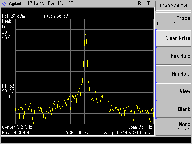
    The picture below is device output which I change the frequency in manual.

    The picture's format is jif, unfortunately the forum can't display it, maybe you should click it.

    2. I didn't use ramp function , I use MCU to change the device frequency in manual.

  • KcMeter,

    I can see the picture in your post. I notice that the output frequency is off, which is suggesting that the input reference you are using is not SYNCed up to the spectrum analyzer that you are using. If you are using an XO or TCXO and that is drifting around, then our device will track this. Could this be the source of the instability you are seeing.

    I note that the spurs are about 5 kHz spacing. I doing see anything in your settings that would suggest 5 kHz spurs. As a diagnostic, you can try disabling the MASH_RST_N but to see if there is any impact, but I suspect that there will be none. The other consideration is the power supply. If you have anything on our supply at 5 kHz, then this will produce 5 kHz spurs on our output.

    Regards,
    Dean
  • Bingo!

    I clear the bit MASH_RST_N, and the spur is disappear!

    Thank a lot!.

  • KcMeter,

    OK, I'm going to assume this is resolved.