This thread has been locked.

If you have a related question, please click the "Ask a related question" button in the top right corner. The newly created question will be automatically linked to this question.

LMK62E0-156M: Clock circuitry to ADC

Part Number: LMK62E0-156M

Hello,

I am designing ADC interface prototype as my project and I am interested in LMK62E0-156M; LVPECL output (I'm also considering higher frequency ones as well).

The ADC requires very low jitter, so I think LMK62E0 would be one of the best solution as the ADC clock source. When I see the reference design in the ADC datasheet, the clock circuitry looks like below figure.

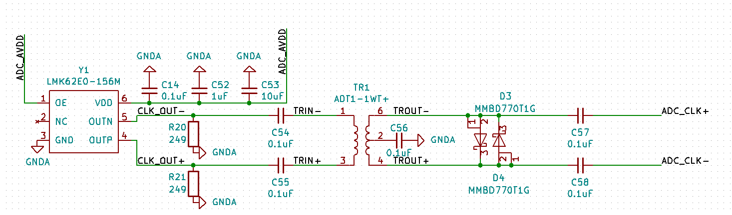
Of course, the Y1 in the reference design was a general XO and I just configured it by LMK62E0-156M without any consideration. From the above design, my question is whether I really need the transformer.

The ADC offers a common voltage reference to the clock signal, so the clock must be AC coupled - which can be achieved by AC coupling capacitors (C57 & C58 in above figures). In that sense, I have a lack of understanding what the role of the transformer is in above configuration. 

(1) If I solely use LMK62E0-156M's LVPECL output only with the termination resistors (R20 & R21) and coupling capacitors (C54 & C55) to provide ADC clock source, could there be any problem?

(2) If Q1 is possible, which configuration would be beneficial to provide the lowest jitter? (With or without transformer)

For some comments or recommendations, it would be very much appreciate.

  • Which ADC part number are you using?  Which reference design did you use?

    Alan

  • Hi Alan,

    The ADC that I consider is AD9269 from Analog Devices. The reference design is UG-200, it is for AD9467 though. I only referred the clock circuitry part, which is shown in page 11 in UG-200.

    Thanks!

    Seongjun

  • A step-up transformer is typically used to provide passive gain (without adding noise) to increase the slope (edge rate) of a sinusoidal clock input signal, while clipping diodes limit the amplitude and avoid exceeding the ADC input range. This is a clean way of generating a square-link clock signal.

    Because the LMK62E0-156M generates a LVPECL differential output squarewave with fast edge rate, you do not need the transformer + clipping diodes. You can just use R20 & R21 and C54 & C55 to drive the ADC differential inputs. Just make sure the ADC has proper input termination to match the differential trace impedance.

    Alan
  • Dear Alan,

    I really appreciate you for the kind and clear answer. It was really helpful to clear my understanding.

    Best regards,

    Seongjun