This thread has been locked.
If you have a related question, please click the "Ask a related question" button in the top right corner. The newly created question will be automatically linked to this question.
Hi support team,
I'm running a 2-board AD sample test, and find an issue that every time after power on the board, the phase of the board is not the same:
Cycle 1: the phase difference is 120 degree;
Power off and on
Cycle2: the phase difference is 260 degree;
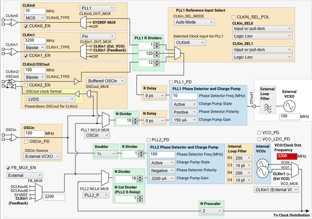
Each board contains an LMK04828 and an LMX2582 to generate 3.2GHz sample clk feed into the ADC12DJ3200. And I use an external 10MHz into the LMK04828 (CLKin0), I can see both lock detect LEDs are ON. So I think PLL1 and PLL2 are phase locked.
Is there any way to keep phase difference the same when everytime the board is powered on?
Regards
Joseph
Let me explain it in more detail, the whole system is working like this:
And the RegMap file for the LMK04828 used in TICS Pro is attached:lmk04828.tcs
Here are some snapshots of it:
Further more: although the PLL1 & PLL2 DLD indicator is On, but as my observation, the phase error between the CLKin0 and DCLKout8 is not the same at every power cycle time.
Can anyone point out my mistake? Or any suggestion is welcome. Thanks.
Regards
Joseph
Wrong feedback path setting.
If you would like to make CLKin0 and OUT8 have deterministic phase relationship, feedback source should select "DCLKout8".
Refer to "Figure 20. Simplified Functional Block Diagram for Nested Zero-Delay Dual-Loop Mode" to set correct FB_MUX, PLL1_NCLK_MUX and .PLL1 N divider.
Hi Shawn,
Thanks for the tip.
Now I configure the LMK04828 like this, and the configuration order is:
1st: write all the registers in numeric order;
2nd: set SYSREF_MUX to Normal, and set SYNC_MUX to pin, turn on all the blocks and enable syncing of all clock outputs and then toggle SYNC_POL on-off-on, disable syncing of all clock output, set SYSREF_MUX to continuous:
3rd: SYNC Dividers just like the TICS Pro "SYNC Dividers" button does
Then I found these 2 board got samples at fixed phase relationship from time to time.
It's about -135 ~~ -137 degrees at 3.2G sample rate and 400MHz signal in.
And my further question is: since these 2 boards are the same, why the phase relationship is -137 degrees? Should it be around 0 degree? Is there modification I need to make?
Regards
Joseph
In Nested Zero-Delay Dual-Loop Mode, OSCout can't setup a fixed phase relationship with reference input.