This thread has been locked.

If you have a related question, please click the "Ask a related question" button in the top right corner. The newly created question will be automatically linked to this question.

RTOS/EVMK2G: EVMK2G changing sample rate has to effect

Part Number: EVMK2G

Tool/software: TI-RTOS

I've tried searching the forums for this problem, but it seems that anything similar is for another platform, so I decided to make a post regarding the EVMK2G specifically.


I'm using the 3.01 TI-RTOS SDK, and only need to get the mcasp loopback example working (the AIC31_Stereo_Loopback example).  As of now, the loopback works, but I can't change any parameters such as the codec gain, or sample rate.  It looks like AIC31SampleRateConfig never gets called in Aic31.c (around line 525 -> 527 -> 529) because it fails the branch `if (ICodec_OpMode_MASTER == instHandle->acOpMode)`.

There's a #ifdef that sets up the codec's opmode in the parameter structure in Aic31.c line 85.  In the makefile MCASP_MASTER is defined. This is the code:

const Aic31_Params Aic31_PARAMS = {
    ICodec_CodecType_AIC31,         /* acType                 */
    ICodec_ControlBusType_I2C,      /* acControlBusType       */
    "NONE",                         /* acCtrlBusName          */
#if defined (MCASP_MASTER)
	ICodec_OpMode_SLAVE,           /* acOpMode               */
#else // MCASP is slave
	ICodec_OpMode_MASTER,           /* acOpMode               */
#endif
#if defined DSP_MODE
	ICodec_DataType_DSP,
	(uint32_t)ICodec_SlotWidth_16,    /* acSlotWidth            */
#else
	ICodec_DataType_I2S,            /* acSerialDataType       */
	(uint32_t)ICodec_SlotWidth_32,    /* acSlotWidth            */
#endif

    ICodec_DataPath_TXRX,           /* acDataPath             */
    0,                              /* isRxTxClockIndependent */
};

Is this line correct?  It's what's preventing the code from making the sample rate configuration call.

#if defined (MCASP_MASTER)
	ICodec_OpMode_SLAVE,


It might be right, but it just looks like a red flag to me.  However, if I switch this around, then the loopback no longer works.  I hear nothing; and the Audio_echo_Task callback is never fired.


Is there any way I can get some help setting up the sampling rate on the EVMK2G with the TI-RTOS 3.01 PDK?  It's stuck at what sounds like a very low sampling rate right now.

  • I've moved your thread to the device forum.

    Todd
  • I know it's the holidays, but does anyone by chance have any suggestions regarding my question and setting the sample rate of the board?

    Thanks.
  • Sorry for the delay in responding to this issue Justyn.

    I looked at the AIC3106 datasheet and  it appears that the maximum sample rate that it can support is 96Khz.

    The default  setup on the base EVM board is such that McASP is the clock master to the AIC3106.  The issue you’re going to have is that the McASP derives its clocks from K2G’s audio oscillator, which runs off of a 22.5792 MHz crystal, which will let you generate 44.1 kHz, 88.2 kHz, etc.  If you want to generate 48 kHz, 96 kHz, etc, just swap that crystal for a 24.576 MHz crystal, then play with the McASP’s clock dividers accordingly

    For the base EVM board with McASP-AIC3106, you should be able to get to 88.2 Khz transmit clock by changing the bit clock divider for 8  to 4 in the ACLKXCTL configuration.

    #if defined (MCASP_MASTER)
            #if defined (DSP_MODE)
    			/* .aclkxctl  = */ 0x00000023, /* Changed to Div(4). It was previously set to Div(8) in example */
    			/* .ahclkxctl = */ 0x00008001, 

    Please give this a try and let me know if this helps you to get to 88.2Khz. If you use the audio daughter card there is a different ADC(PCM1865) that can support upto 192Khz sampling rate.

    Regards,

    Rahul

  • I will update you tomorrow with my findings.

    We do indeed have the AUDK2G audio daughtercard, and will absolutely need to move to that for the goal of the project, but last I heard, there was no example code in the SDK, instead was planned on being released in the "new version" of the SDK, as per here:

    e2e.ti.com/.../549770

    However, is there any updates on the new version of the SDK? Is it available? Will example code for the AUDK2G board indeed be in it?

    I was going to save AUD questions for later on when I got to try out the new SDK, when it comes out. But any update there would be awesome as well.
  • It seems like this change has no effect.

    To illustrate what I'm hearing, I've recorded 4 audio events on a separate laptop.  There's sometimes clicks in the audio, but it's just because I'm using a laptop to record audio with its built-in interface, so It's not so great.  The separate events are in FLAC format, and should be able to be played on any media player.

    There are two sine wave sweeps that have been recorded at 1) the line in of the EVMK2G and 2) the line out of the EVMK2G.  The output has extremely obvious aliasing effects happening.

    There are also two audio files that are just me speaking.  They are again recorded at the input and output of the EVM board.  Here, again, you can obviously tell that the sample rate is NOT 88.2kHz.  Nor is it 44.1.  It's something extremely low as is evident when you hear it.

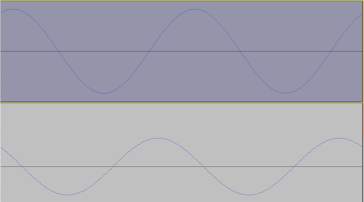
    I'll also provide an image of the sine wave audio input and output waveforms.  Even visually it's obvious that there's a lot of aliasing happening, which, again, implies a very low sample rate.  I'll let you guess which image is from the input and which is from the output.

    Files:

    audioEvents.zip


  • I think the problem is that I'm not understanding the math here.

    In the EVM example, the following registers are set (they're the same for TX/RX).
    /* .aclkxctl = */ 0x00000027,
    /* .ahclkxctl = */ 0x00008001,

    So, the high-frequency clock register is using the AUXCLK source with a divider of 2.
    The regular clock control is using the internal output from the high clock source, with a divider of either 4, or 8 (the numbers we tried).

    Okay, so according to what you said, if our audio oscillator is 22.5792MHz, then the rate of our "internal functional TX (or RX) clock" I understand it as it should be 22579200 / 2 / 8, which is 1411.200kHz, if we're using DIV(8).

    That makes no sense. Can you pinpoint where I'm not understanding how the clock generator blocks work? I'm referencing the TRM pg. 2608 for the functional block diagram.

    When I select DIV(0), I hear no audible aliasing. When I select DIV(32), I hear a lot of degradation. This is expected by dividing the clock by 1, then again by 33. However, again, DIV(4) and DIV(8) both sound very low-sample rate.

    What is the correct way to figure out the math to determine the function TX/RX sample rate, given our 22.5792MHz Audio Oscillator?
  • Justyn,

    Your calculation is correct. 1411.2 is the correct value of transmit clock required for 44.1 Khz sampling rate.

    The transmit clock is the bit clock used to send the data. Each audio data sample(I2S format) has 2 channels and each channel is 16 bits in our configuration. So to send a data sample(2 channels) you will need 44.1*2*16 = 1411.2 Khz bit clock.


    Therefore to get 88.2 Khz sampling, you need a 2822.4 Khz bit clock. which can be achieved by reducing the transmit clock divider from 8 to 4. the configuration is in sync mode so as soon as you change the transmit side, the receive side will change accordingly.

    Regards,
    Rahul

  • Okay, hang on a second.

    In the recommendations above, you said to set

    #if defined (MCASP_MASTER)
            #if defined (DSP_MODE)
                /* .aclkxctl  = */ 0x00000023, /* Changed to Div(4). It was previously set to Div(8) in example */
                /* .ahclkxctl = */ 0x00008001,


    This code is in the DSP_MODE block.

    I noticed that you have a #define DSP_MODE commented OUT at the top of the file.  Maybe you meant for that to be #undef DSP_MODE? Nevermind, it's set in the makefile, it looks like.

    Are we supposed to be in DSP mode or I2C mode?

  • Justyn,

    The code is configured in DSP_MODE and is using single 32 bit wordlength. You can see this in the mcasp_chanparams. We have frequently observed this confusion when working with 16 bit data .  When working with MCASP-EDMA and 16 bit data, there is a 32 bit access requirement due to which we define DSP_MODE which configures the wordlength as 32 and uses a single slot to receive both left and right channel data.

    Please read about this 32 bit access requirement on the MCASP tips wiki :
    processors.wiki.ti.com/.../McASP_Tips

    Incase we are working with 32 bit data samples as in case of the AM572x EVM, we configure I2S_MODE macro and use 2 different slots to capture the 2 separate samples but with 16 bit data we use single 32 bit slot to get both channels.

    I hope this helps.


    Regards,
    Rahul

  • The explanation for DSP mode on the EVMK2G board makes sense.  But no, this has not helped the status of the board overall.

    I have come to the following conclusions:

    1) If I set the divider to 1, I can hear clear, high bandwidth audio.  If I set the divider to 32, its maximum value, I can hear extremely low bandwidth audio.  This leads me to believe that I am indeed changing the sampling rate when I set the extremes.

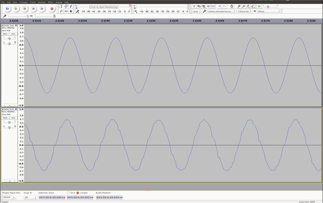
    2) If I set the divider to 4, I hear audio that is definitely NOT 88.2 or even 44.1KHz audio.  Attached below is an Audacity capture of a 1kHz tone.  That is, I used an external laptop to generate a 1kHz tone.  I captured the signal going into the Line input of the EVM board, and what comes out of the Line output of the EVM board.  This was taken just right now with the divider set to 4 (/* .aclkxctl  = */ 0x00000023).  This was using PDK 1.0.3.  I tried with the AIC loopback example in pdk 1.0.4, but I was getting data verification errors that I don't have time to look through.

    As I mentioned, I am going using the AUDK2G daughtercard, but the configuration involves hitting the same registers, and going through the same process.  Our researchers have designed algorithms that RELY on a certain sample rate.  And if I can tell audibly that what you're saying is supposed to be 44.1 or 88.2 is nowhere near that, I'm hesitant to move forward and expect the results we're looking for.

    I will invariably have questions regarding the AUDK2G, but I will open them in a separate thread.  I would advise you guys to try the AIC31 loopback in house, and verify that setting DIV(8) or DIV(4) results in very poor performance.


    Thanks for the responses in this regard,

    Justyn

  • Justyn,

    I did some more measurements with this setup and here are my observations. I measured the bit clock ACLKX and AFSX with the default 44.1 Khz setup and here is the clock at 1411.2 Khz and the FSX at 44.1 Khz with Single slot, Wordlength of 2 as we expected. 

    I then proceeded to chnage the ACLKX divider to (3) to check if the frame sync chnage accordingly and again as expected the ACLKX was observed as 2822.4 and FSX at 88.1 so the change does have the desired effect.


    I also used a known SineWave audio signal and captured the data received with the frame sync. I also hear the audio loopback working as expected with the 88.2 Khz setting Are you sure the way you are recording the audio is setup correctly?

    Regards,

    Rahul

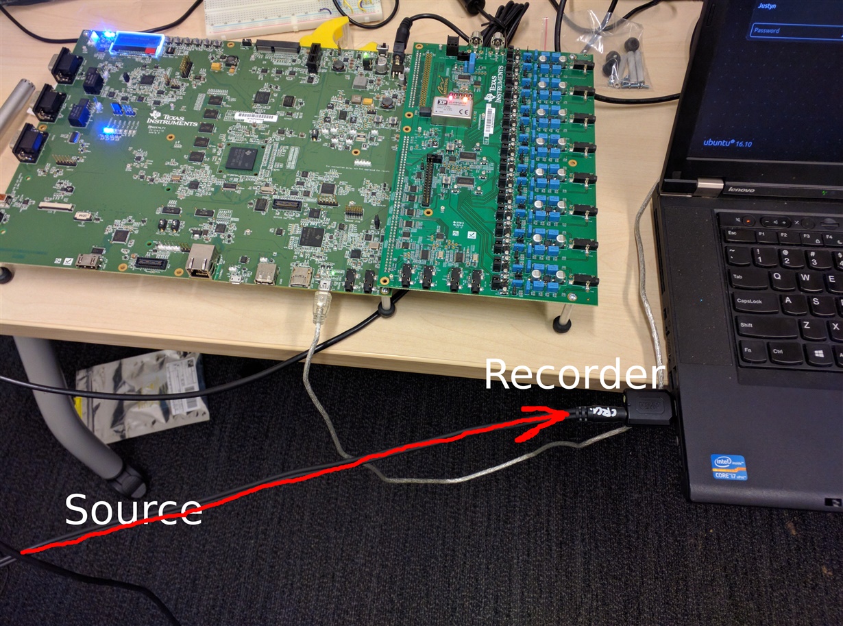
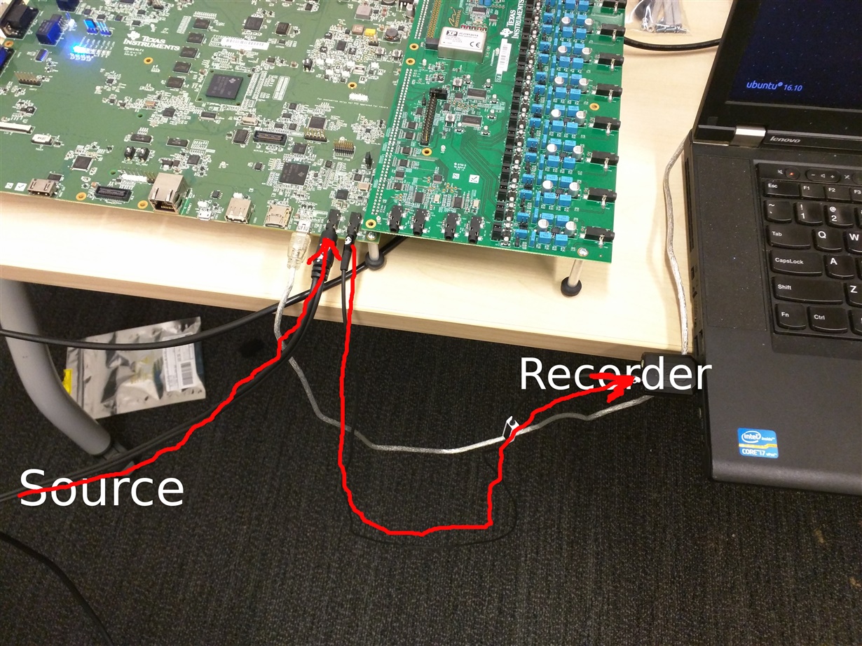
  • Here is the setup.  The source is an audio interface outputting a sine wave.  The only variable that changes is adding the extra cord that goes from the EVM to the recording computer.  However, I also can plug headphones into the line out, and hear the aliasing as well.  So it's not the cable.

    I don't doubt that the clocks are working correctly, or that your math is correct.  But maybe there's something else going on here.  Maybe the LPFs on the DACs?  The impedance on the line in/outs?  I have no idea.  I know you've spent a long time on the problem, but it would be interesting if you were able to record that sine wav and provide it here.  So we could listen and view its samples such as what I did with Audacity.

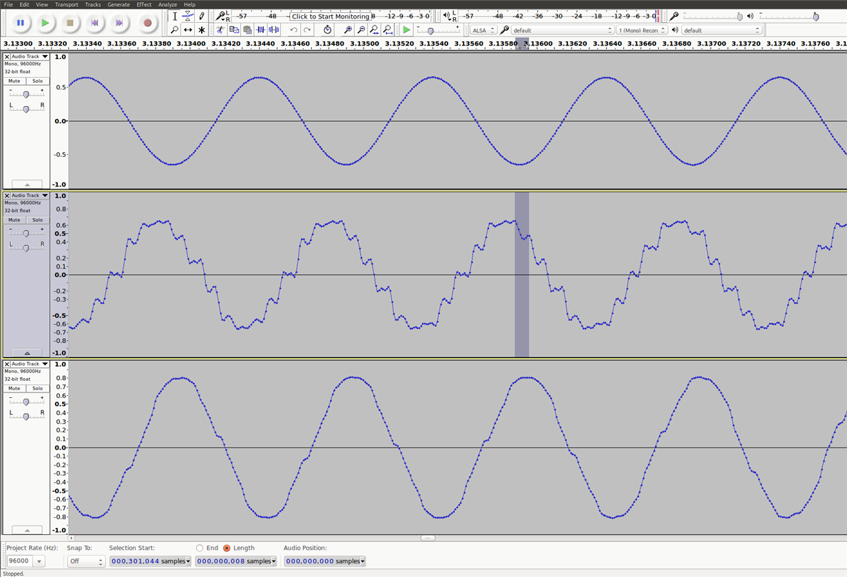
    Recording the clean signal (above in the Audacity screen shot).


    Loopback (bottom picture in Audacity screenshot.

  • I had a little bit of time and recorded some more audio with a 1kHz sine wave.  This time with the divider set to 1, 32, and 8, set respectively in the Audacity screenshot.  With the divisor set to 32, I expect an audio rate of 11.025kHz.

    If my Audacity program is set to record at 96kHz, and I assume the output of the EVM board is not lowpassed, for every sample of the 11.025kHz output, my program should have ~8.7 samples representing it.

    Indeed, that's about what I see:

    I then downloaded the TLV320AIC31 manual, and there's no entries for "low pass filter" except this:

    "All performance measurements made with 20-kHz low-pass filter and, where noted, A-weighted filter. Failure to use such a filter may result in higher THD+N and lower SNR and dynamic range readings than shown in the Electrical Characteristics. The low-pass filter removes out-of-band noise, which, although not audible, may affect dynamic specification values."

    Can you confirm that

    1) The DAC has no LPF

    2) In the face of a DAC without a LPF, what I'm seeing is correct

    3) My hypothesis is correct: the output waveform is jagged because there's no LPF.  This introduces high-frequency components, which a user can hear in both 44.1 and 88.2kHz.  I mistook this for poor sample rate instead of high-frequency content (I guess aliasing wasn't the right prediction at the beginning).

    4) The AUDK2G DAC do contain LPFs.  Because I hear no high-frequency content in the AUD loopback as I do here.

  • Justyn,

    thanks for the additional experiments with this setup and also for the waveforms. Yes, the audio daughtercard is really meant for better audio output as compared the base board.

    For the AIC codec questions, can you please post your questions to Audio Converter forums:
    e2e.ti.com/.../

    I appreciate your patience with this issue.

    Regards,
    Rahul