This thread has been locked.

If you have a related question, please click the "Ask a related question" button in the top right corner. The newly created question will be automatically linked to this question.

TIC12400EVM-KIT: TIC12400 EVM and External Micro Interface over SPI

Part Number: TIC12400EVM-KIT
Other Parts Discussed in Thread: TIC12400, TXB0106, TIC12400-Q1

Hi 
I am new with MSDI &  trying to interface TIC12400Q1 EVM SPI Communication with External Microcontroller(NXP: S32K118)
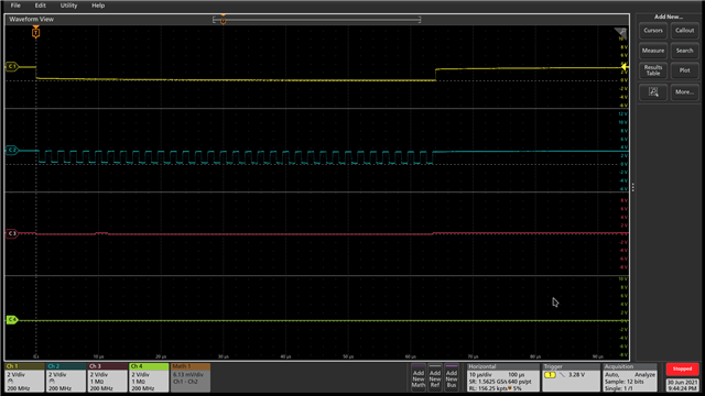
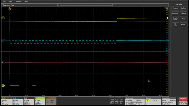
So i am transmitting 0x02000000 (DEVICE_ID) and trying to read but i am Receiving 0xe0000003 (POR, SPI FAIL, PARITY FAIL).

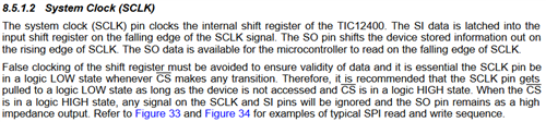
With GUI everything working fine bit with external microcontroller i am not able to read even the SPI.

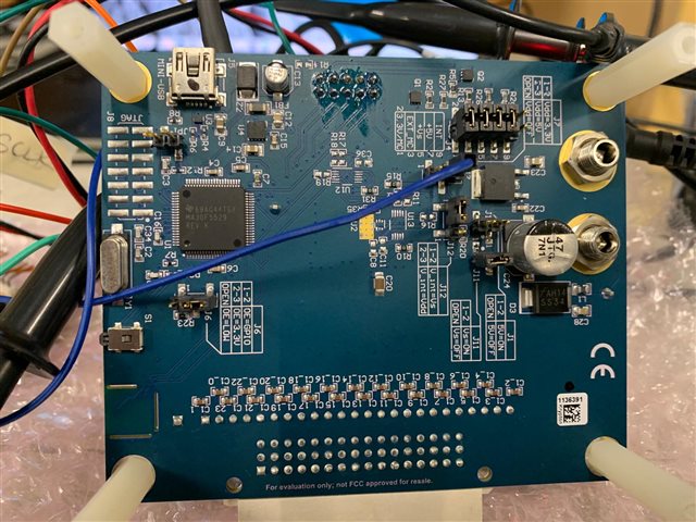
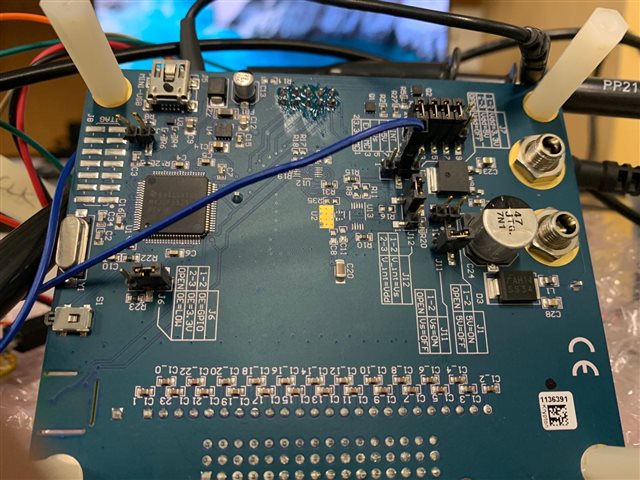
Is there any specific Jumper setting i am missing?

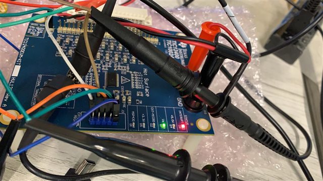
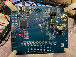
For connection i am referring below mention link.

https://e2e.ti.com/support/interface-group/interface/f/interface-forum/708256/tic12400-how-to-test-tic12400-evm-board-from-external-microcontroller-through-spi-commands?tisearch=e2e-sitesearch&keymatch=TIC12400#


  • Salim,

    An applications engineer has been notified of this thread and will respond today.

    Regards,

    Eric Hackett 

  • Hi Salim,

    The settings in the link you referenced should work. 

    Can you confirm the connections and jumper settings you are using, or provide a picture of your board and jumper settings and cables that I can review?  Perhaps there is something you have overlooked.

    Do you have the USB cable connected when you have the external MCU connected, or are you using an external supply for the TIC12400 VDD?

    Can you provide any scope plots of the SPI signals?  Using an external MCU for the SPI connections can result in reflections and noise on the SPI signals which could result in bit errors.  There could also be a timing or protocol error that is resulting in the SPI communication errors.

    Examples of a protocol error are:

    • The CS signal does not stay low for all 32 bits of the SPI transaction.  For example, many MCU SPI drivers R/W 8 bits at a time and the CS signal is transition every 8 bits.  This will lead to an error for the TIC12400.
    • There is a phase delay between the clock and data.  The TIC12400 clocks data on the Falling Edge.
    • The MSB/LSB order may be inversed.

    If you can provide details of your configuration and scope plots of your SPI communication, I can review it for errors.

    Regards,

    Jonathan

  • Hi Jonathan 
    thanks  & appreciate your support.

    SPI Configuration : 500000Hz, CPOL =0, CPHA =0.

    Do we have to follow any specific mode of SPI?

    I am not connecting board with USB. I have removed J7 jumper and e connected VCC(3.3V) from my board to pin2 of the jumper J7.

    I have verified the 3.3V connected to J7(Pin-2)

    Below Waveform when Jumper J7 Connected in-between Pin1 &2 (No USB cable connected)
    C1: CS

    C2: Clock

    C3 : MOSI

    C4: MISO

    Below Waveform when Jumper J7 Removed & ExternalMicro_VCC_3.3V Connected to J7-Pin_2 ((No USB cable connected)

    Board Jumper connection Picture

    SPI PIN Connections:

    What i see from waveforms, the level of MOSI & MISO lines is not as expected. 

    While referring the below schematic i have connected VDD with 3.3V (From External microcontroller)

  • Hi Salim,

    Thanks for the pictures and waveforms, they are helpful.  I have noticed a couple of things.

    The MOSI and MISO signal lines are not full amplitude.  You have also noticed this. 

    • The shunt on your JMP6 may not in the correct location.  It would recommend it be located on pins 1-2, or removed completely.  I've highlighted this in the following picture.  If the USB cable is not connected the +3.3V supply should not be present and the TXB0106 Level Shifter should not have power.  The OE jumper should in theory not have any impact on the signals from an external MCU.  However, it should be possible to use and external MCU with a USB cable connected if the OE jumper is not located between pins 2-3.  You could try to remove the shunt to ensure the level shifter is not impacting the signal levels.

    • I think I saw a wire on a GND pin (TP3) which I assume is connected to the MCU, but you may want to add a GND wire to J3 header to make sure there is a good GND for the SPI signals to reference.
    • If the TXB0106 is not loading the signals, double check the wires are correct and there are no other possible loads such as pullup/pulldown resistors, capacitors, etc. on the lines.

    However, for the SPI signal waveforms, I noticed the SCLK polarity is incorrect.  The SCLK needs to be LOW when the CS pin transitions and to ensure there are the correct number of falling edges for the data.  This is described in the SPI Interface Bus section of the datasheet.  I can see a similar MISO waveform with no valid data response from the TIC12400-Q1 when I adjust the SCLK polarity to match yours.  To verify all your polarity settings are correct, I would suggest using your scope to view and compare the CS, SCLK, and MOSI waveforms from the MSP430 MCU using the GUI with the exact same register read/write from your external MCU.

    So to summarize, invert your SCLK polarity and match the SPI waveforms from the GUI and MSP430.  And check for sources that may be loading the SPI signals and reducing their amplitude. 

    Regards,

    Jonathan